

Automatic coiling method for welding wire in welding wire box of submerged arc welding machine
A technology of submerged arc welding machine and electrode box, which is used in the transportation of filamentous materials, thin material processing, transportation and packaging, etc., can solve the problem of poor coiling effect, time-consuming and laborious, and submerged arc welding wire can not be used in standard wire. On the plate and other problems, to achieve the effect of improving the efficiency of the coil wire
- Summary
- Abstract
- Description
- Claims
- Application Information
AI Technical Summary
Problems solved by technology
Method used
Image

Examples
Embodiment 1
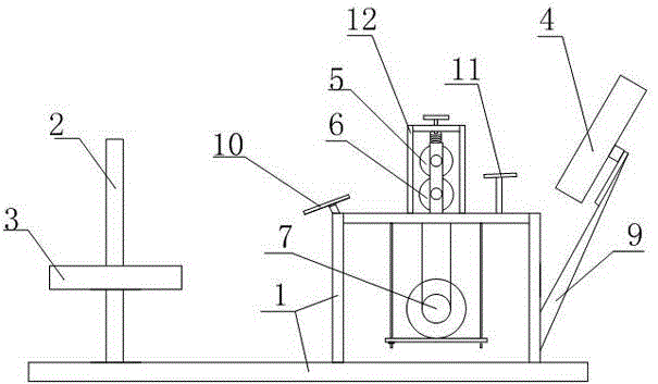
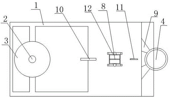
[0022] Such as Figures 1 to 2 As shown, the present invention is an automatic coiling method for welding rods in a submerged arc welding machine welding rod box, which includes a workbench 1, and also includes a wire crimping device connected to the workbench, and a release device respectively located on both sides of the wire crimping device. Wire device and standard wire box 4; the wire pay-off device and standard wire box 4 are connected to the workbench 1 or the crimping device, the axis of the standard wire box 4 forms an angle β with the horizontal plane, and 0<β≤90. A method for automatically inserting welding rods into the welding rod box of a submerged arc welding machine is composed of four parts, a workbench, a wire-feeding device, a wire-crimping device, and a standard wire box. It is connected to the workbench, or the crimping device is connected to the workbench, and the wire-off device and the standard wire box are connected to both sides of the crimping device...
PUM
 Abstract
Description
Claims
Application Information