Slitter edge coiling machine

A side coiling and coiling device technology, applied in the field of waste coiling, can solve the problems of increasing the coiling range, increasing the size of the reel, and affecting the production efficiency, so as to improve the coiling efficiency, improve the control accuracy, and have a simple structure Effect

Active Publication Date: 2015-07-15
CISDI ENG CO LTD
View PDF6 Cites 1 Cited by
  • Summary
  • Abstract
  • Description
  • Claims
  • Application Information

AI Technical Summary

Problems solved by technology

[0003] Existing waste edge coilers are generally designed as an integral structure in which the wiring device and the coiling device are integrated. Although this waste edge coiler can meet the coiling requirements of waste edges to a certain extent, such waste edge The structure of the coiler is complex and bloated, and its manufacturing and production maintenance are difficult. Moreover, because the two reels of the coiler are of fixed structure, it will cause that when the width of the incoming strip steel exceeds the coiling structure during the production process. When the distance between the two reels is adjusted, the reel of the waste edge coiler cannot wind the waste edge in the full length range
In order to solve this problem, the measures taken are often to further increase the size of the reel, or even reduce the taper of the cylinder to increase the coiling range, which makes the waste edge coiler have to Enlarging the size of the equipment, on the one hand, leads to the complexity of the equipment and the increase of the cost. At the same time, it may also cause the waste rolls to fail to automatically fall off normally, which affects the production efficiency.
[0004] The Chinese patent with the publication number CN 101181725 discloses a waste edge coiler, which still adopts an integral structure in which the wiring device and the coiler are designed as one, and the reel, clamping mechanism and rotating The mechanism moves along the length direction of the reel under the action of the wiring hydraulic cylinder of the wiring mechanism. To realize the full-range winding of the reel, the stroke of the wiring hydraulic cylinder is required to be longer, and the distance between the wiring slide and the base The length of the chute is also required to be longer, which not only leads to the defects of large size, complex structure and high manufacturing cost of the waste edge coiler, but also only controls the movement of the reel along the length direction through the wiring hydraulic cylinder during the coiling process. Defects that can lead to poor winding uniformity of scrap

Method used


Image

  • Slitter edge coiling machine
  • Slitter edge coiling machine
  • Slitter edge coiling machine

Examples


Embodiment Construction

[0023] The preferred embodiments of the present invention will be described in detail below with reference to the accompanying drawings.

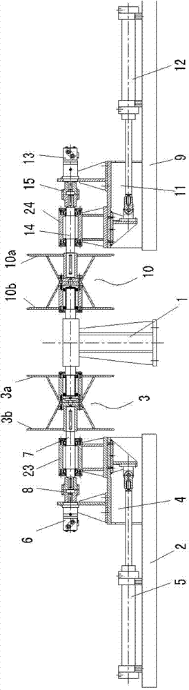
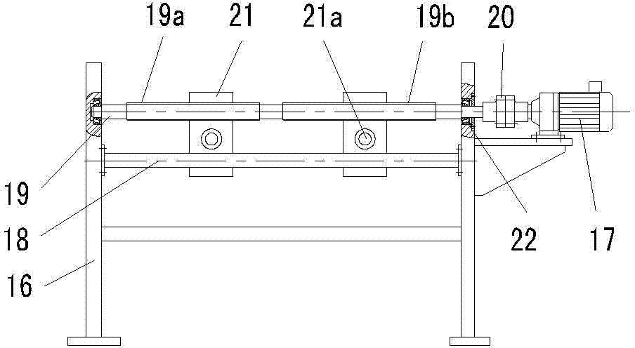
[0024] Such as figure 1 As shown, it is a schematic structural view of the coiling device of the waste edge coiling machine embodiment of the present invention, figure 2 It is a structural schematic diagram of the wiring device of the waste edge coiler in this embodiment. The waste edge coiling machine in this embodiment includes independently arranged coiling devices and a wiring device that cooperates with the coiling devices and is used for guiding waste edges.

[0025] The coiling device includes a coiling support 1 , and a left coiling device and a right coiling device respectively arranged on two sides of the coiling support 1 .

[0026] The left winding device comprises a left base 2, a left clamping device, a left transmission device and a left reel 3. The left clamping device includes a left clamping slide 4 slidingly fitted wi...


PUM


Abstract

The invention discloses a slitter edge coiling machine, which comprises a coiling device and a wiring device, wherein the coiling device and the wiring device are arranged independently respectively; the wiring device is matched with the coiling device, and is used for guiding slitter edges; the wiring device comprises a wiring bracket; a gear motor and a guide lever are arranged fixedly on the wiring bracket; a bilateral lead screw is arranged on the wiring bracket in a way of being rotationally matched with the wiring bracket; the bilateral lead screw and the gear motor rotate synchronously; the bilateral lead screw is provided with a left threaded section and a right threaded section respectively corresponding to a left coiling block and a right coiling block; the left threaded section and the right threaded section are provided with guide blocks which are in threaded fit with the left threaded section and right threaded section respectively; the guide blocks are provided with through holes for sleeving the guide blocks on the guide lever; the axis of the guide lever is parallel to the axis of the bilateral lead screw; and the guide blocks are provided with guide grooves for threading and guiding slitter edges. Due to the adoption of the slitter edge coiling machine disclosed by the invention, full-range coiling of the coiling blocks can be realized, and the coiling uniformity is high; and the slitter edge coiling machine has the advantages of simple structure and low manufacturing cost.

Description

technical field [0001] The invention belongs to the technical field of coiling waste edges cut by disc shears after pickling, and particularly relates to a waste edge coiling machine. Background technique [0002] In the cold rolling production line, the steel plate after pickling needs to be cut by disc shears to meet the width requirements of the finished strip. At present, there are mainly two ways to deal with the waste edges cut by disc shears: one is to directly chop the waste edges, and then return the chopped waste edges to the furnace; the other is to roll the waste edges into regular Steel coils, which can be used as raw materials for the hardware and metal products industry, and can be sold like finished steel coils. From the waste edge utilization benefits after the two ways of treatment, it is not difficult to see that the waste edge coiling has a very high economic value, therefore, the waste edge coiler is widely used. [0003] Existing waste edge coilers ar...

Claims


Application Information

Patent Timeline
Patent Type & Authority Patents(China)
IPC IPC(8): B21C47/04B21C47/34
Inventor 高爱民
Owner CISDI ENG CO LTD
Why Eureka
Try Eureka