
Water flow wedge conveying device for rockery

A conveying device and wedge-type technology, which is applied in the field of water flow wedge-type conveying devices, to achieve the effects of reducing excavation depth, reducing engineering construction costs, and saving energy

Inactive Publication Date: 2018-03-02
CHONGQING GENYU GARDEN LANDSCAPE ENG CO LTD
View PDF5 Cites 0 Cited by
  • Summary
  • Abstract
  • Description
  • Claims
  • Application Information

AI Technical Summary

Problems solved by technology

[0003] The present invention intends to provide a water flow wedge conveying device used on rockery to solve the problem of combining people's pressure and water circulation

Method used


Image

  • Water flow wedge conveying device for rockery

Examples


Embodiment Construction

[0014] The present invention will be described in further detail below by means of specific embodiments:

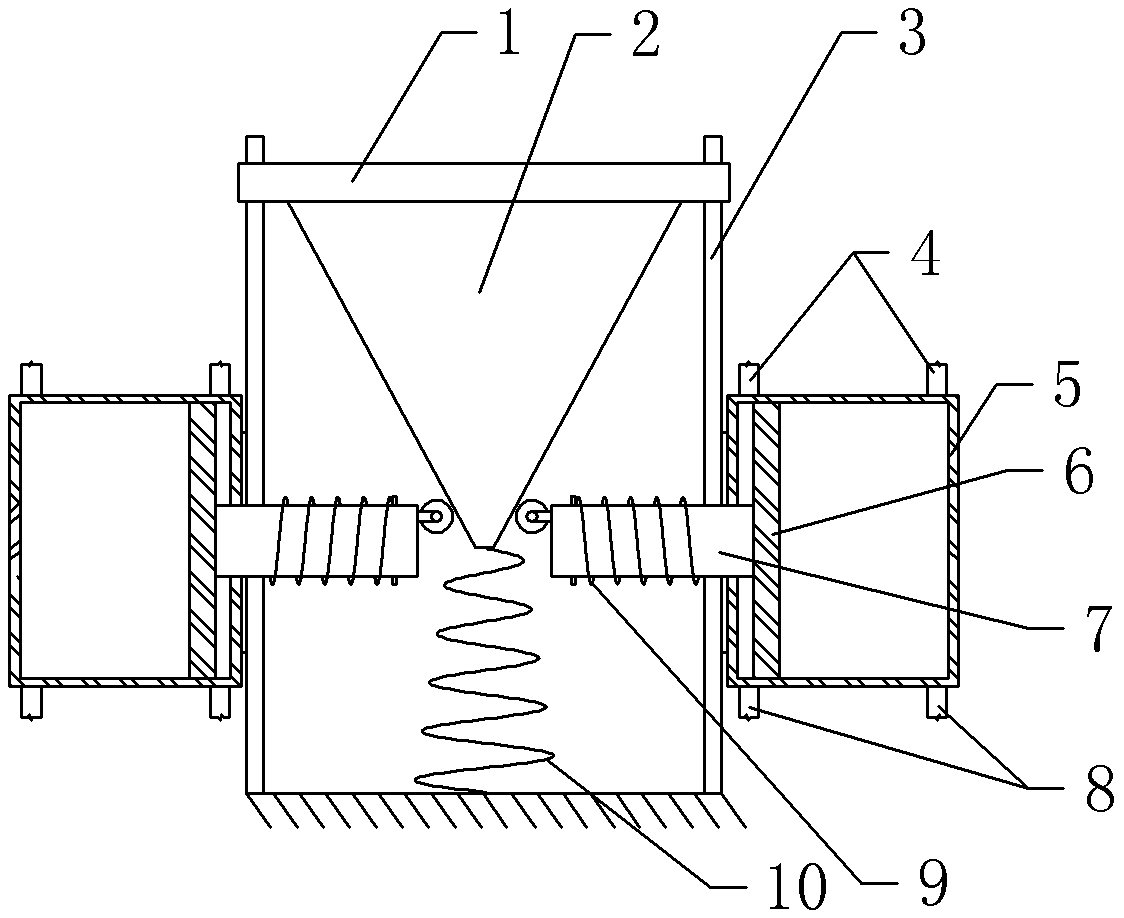
[0015] The reference numerals in the drawings of the description include: support plate 1, wedge 2, bracket 3, water inlet pipe 4, pump body 5, piston 6, piston rod 7, water outlet pipe 8, spring 9, tower spring 10.

[0016] like figure 1 The shown water flow wedge conveying device for rockery includes a bracket 3, and the bracket 3 is embedded and installed on the pool wall. A right horizontal support plate 1 is provided on the support 3, and the support plate 1 is slidably connected with the support 3. The lower end of the support plate 1 is fixedly connected with a wedge 2, and the left and right sides of the wedge 2 are provided with inclined surfaces. The lower end of the wedge 2 is provided with a tower spring 10 . Two piston pumps are arranged below the support plate 1, and the two piston pumps are arranged symmetrically with the central axis of the wedge 2 as t...


PUM


Abstract

The invention discloses a wedge block type flow delivery device used for an artificial hill. The wedge block type flow delivery device comprises a power mechanism. The power mechanism comprises a support. The support is provided with a transverse supporting plate. The supporting plate is slidably connected with the support. The lower end of the supporting plate is fixedly provided with a wedge block. Piston pumps are arranged below the supporting plate and each comprise a pump body, a piston and a piston rod. The pump bodies are fixedly connected with the support and are transversely arranged. A pump cavity is formed in each pump body. The pistons are in tight sliding fit with the inner sides of the side walls of the pump bodies. The piston rods and the pump bodies are coaxially arranged. The piston rods are fixedly connected with the pistons and are in tight sliding fit with the pump bodies. The left ends of the piston rods abut against the inclined faces of the wedge block. The support is provided with springs making the piston rods move away from the corresponding pump bodies. The right end of each pump body is provided with a water inflow pipe and a water outflow pipe. Both the water inflow pipes and the water outflow pipes are provided with one-way valves. The water outflow pipes are connected into the top of the artificial hill. The wedge block type flow delivery device has the beneficial effects that energy consumed in the flow delivery process is saved, and the better environment protection effect is achieved.

Description

technical field [0001] The invention relates to water flow conveying equipment for landscape gardens, in particular to a water flow wedge type conveying device used on artificial hills. Background technique [0002] Rockery is a commonly used structure in garden landscape. In order to increase the ornamental quality of the rockery, water flow is often set on the rockery, a pool is set at the bottom of the rockery, water is taken from the pool by a water pump, and the water is pumped to the top of the rockery to make the water flow form circulating water. The water pumps used in water circulation are generally driven by electricity, which consumes a lot of electric energy. In order to increase the practicability of the landscape, a circle of pool walls is often set up on the edge of the pool at the bottom of the rockery for people to sit on it to rest, chat, take pictures, etc. The average mass of a person is about 50 kilograms. When people sit on the pool wall, the pool wa...

Claims


Application Information

Patent Timeline
Patent Type & Authority Patents(China)
IPC IPC(8): F04B9/14F04B23/06
CPCF04B9/14F04B23/06
Inventor 马朝宇
Owner CHONGQING GENYU GARDEN LANDSCAPE ENG CO LTD
Learn More