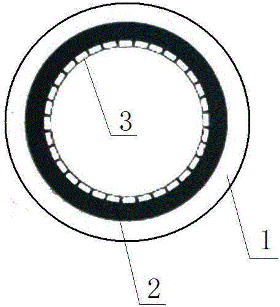
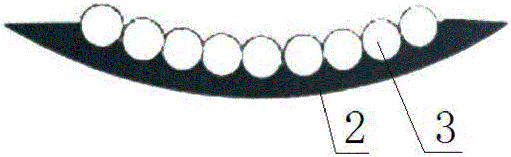
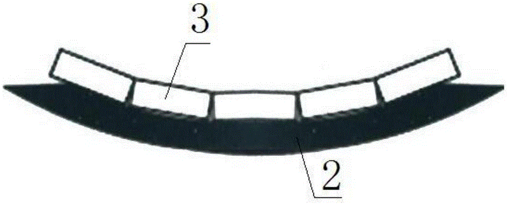
Dust removal pipeline
A technology for pipes and steel pipes, applied in the field of dust removal pipes, can solve the problems of blockage of dust removal pipes, wear through pipes, waste of resources, etc.
- Summary
- Abstract
- Description
- Claims
- Application Information
AI Technical Summary
Problems solved by technology
Method used
Image

Examples
Embodiment 1
[0034] Embodiment 1: The preparation scheme is the above method, and its semi-finished rubber formula is 54 parts of silicone rubber, 27 parts of butyl rubber, 1 part of stearic acid, 1 part of terpene resin, 1 part of white carbon black, 1 part of spray carbon black, 1 part of high wear-resistant carbon black, 0.8 part of accelerator MBTS, 0.81 part of anti-aging agent RD, 2.51 parts of sulfur, and 0.5 part of dioctyl ester.
Embodiment 2
[0035] Embodiment 2: the preparation scheme is the above method, and its semi-finished rubber formula is 66 parts of silicone rubber, 36 parts of butyl rubber, 4 parts of stearic acid, 4 parts of terpene resin, 3.5 parts of white carbon black, 5 parts of spray carbon black, 7 parts of high wear-resistant carbon black, 1.2 parts of accelerator MBTS0, 1.2 parts of antioxidant RD, 3.5 parts of sulfur, and 1.8 parts of dioctyl ester.
Embodiment 3
[0036] Embodiment 3: the preparation scheme is the above method, and its semi-finished rubber formula is 61 parts of silicone rubber, 31 parts of butyl rubber, 3 parts of stearic acid, 2 parts of terpene resin, 2 parts of white carbon black, 3 parts of spray carbon black, 4 parts of high wear-resistant carbon black, 1 part of accelerator MBTS, 1 part of anti-aging agent RD, 3 parts of sulfur, and 1 part of dioctyl ester.
PUM
 Abstract
Description
Claims
Application Information
 - R&D Engineer
- R&D Manager
- IP Professional
- Industry Leading Data Capabilities
- Powerful AI technology
- Patent DNA Extraction
Browse by: Latest US Patents, China's latest patents, Technical Efficacy Thesaurus, Application Domain, Technology Topic.
© 2024 PatSnap. All rights reserved.Legal|Privacy policy|Modern Slavery Act Transparency Statement|Sitemap