Floor heating plate structure

A floor heating board and warm board technology, applied in the field of room floor heating, can solve problems such as hollowing and cracking, and achieve the effect of preventing hollowing

Inactive Publication Date: 2016-05-11
肖玉化
View PDF1 Cites 2 Cited by
  • Summary
  • Abstract
  • Description
  • Claims
  • Application Information

AI Technical Summary

Problems solved by technology

[0003] The invention aims at the problem that if the concrete is directly laid on the floor heating panel module, it is easy to produce hollowing, cracking, etc., which further affects the decorative effect of the floor, and provides a floor heating panel which can prevent hollowing and cracking of the concrete and does not affect the decorative effect of the floor structure

Method used


Image

  • Floor heating plate structure
  • Floor heating plate structure

Examples


Embodiment Construction

[0013] The present invention will be further described below in conjunction with the accompanying drawings.

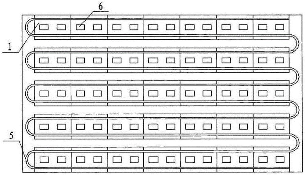
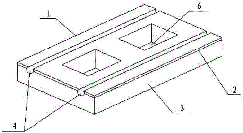
[0014] Such as figure 1 , figure 2 In the shown embodiment, a floor heating panel structure includes several rectangular floor heating panel modules 1. The floor heating panel module 1 includes an upper metal heat conducting layer 2 and a lower layer of polyethylene heat insulating layer 3. There are two parallel recesses on the floor heating panel module 1. Groove 4 is used for placing the floor heating coil 5. Floor heating panel modules 1 are arranged end to end in parallel rows. There is a spacing between the rows of floor heating panel modules. There is a spacing between the two ends of the floor heating panel module row and the room wall. Two through holes 6 are arranged between the upper two parallel grooves 4, and the distance between two adjacent rows of floor heating coils 5 in the row of the floor heating panel module 1 is equal to that of the floor heatin...


PUM


Abstract

The invention discloses a floor heating plate structure which comprises a plurality of rectangular floor heating plate modules, wherein each rectangular floor heating plate module comprises an upper metal heat-conducting layer and a lower polyethylene heat-insulating layer; two parallel grooves are formed in each floor heating plate module for allowing floor heating coil tubes to place; the floor heating plate modules are connected end to end so as to be in parallel arranged into rows; a spacing is arranged between the floor heating plate module rows; a spacing is arranged between the two ends of each floor heating plate module row and a room wall; at least one through hole is arranged between the two parallel grooves in each floor heating plate module; the spacing between adjacent two rows of the floor heating coil tubes in the floor heating plate module rows is equal to that of the floor heating coil tubes on the corresponding floor heating plate module; the metal heat-conducting layer is a carbon crystal plate which is provided with a wear-resisting layer, a carbon crystal layer and a bottom aluminum plate layer from top to bottom; and sections of the grooves in the floor heating plate modules are in the shape of inverted Omega. The floor heating plate structure can prevent concrete from empty drums and cracks, so that the ground decoration effect is not affected.

Description

technical field [0001] The invention relates to the technical field of room floor heating, in particular to a floor heating panel structure. Background technique [0002] With the improvement of residential living conditions, more and more families choose to use floor heating to heat the room, that is, laying floor heating panel modules on the ground, and then covering the floor heating panel modules with floor decoration materials. Choice, some families choose flooring, some families choose stone or floor tiles, and when installing stone and floor tiles, the bottom needs to be bonded with concrete. If concrete is directly laid on the floor heating panel module, it is easy to produce empty drums, Cracking, etc., which will affect the decorative effect of the ground. Contents of the invention [0003] The invention aims at the problem that if the concrete is directly laid on the floor heating panel module, it is easy to produce hollowing, cracking, etc., which further affe...

Claims


Application Information

Patent Timeline
Patent Type & Authority Applications(China)
IPC IPC(8): F24D3/14
CPCF24D3/146F24D3/141
Inventor 肖玉化
Owner 肖玉化
Why Eureka
Try Eureka