Vortex flowmeter including pressure pulsation amplitude analysis

A vortex flowmeter and vortex technology, applied in the field of vortex flowmeter, can solve the problems of inaccurate flow measurement value of vortex flowmeter

Active Publication Date: 2016-05-11
INVENSYS SYST INC
View PDF6 Cites 1 Cited by
  • Summary
  • Abstract
  • Description
  • Claims
  • Application Information

AI Technical Summary

Problems solved by technology

In either case, this would cause inaccurate flow measurements from

Method used


Image

  • Vortex flowmeter including pressure pulsation amplitude analysis
  • Vortex flowmeter including pressure pulsation amplitude analysis
  • Vortex flowmeter including pressure pulsation amplitude analysis

Examples


Embodiment Construction

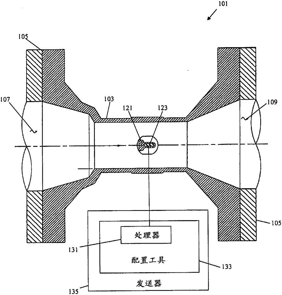
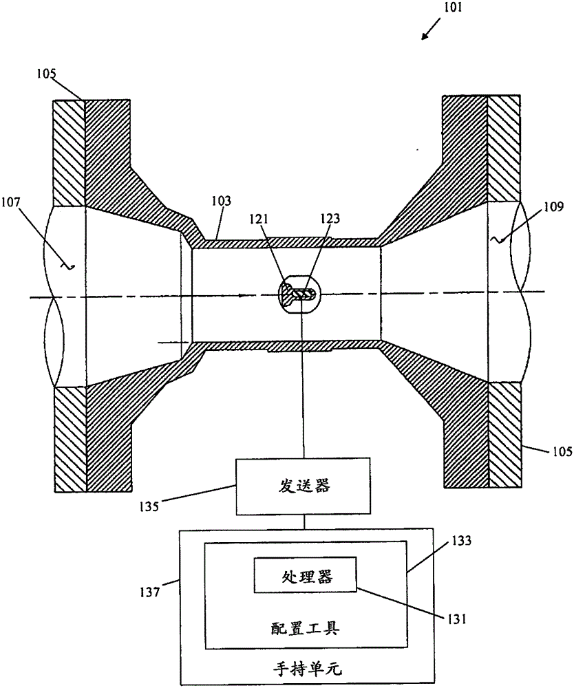
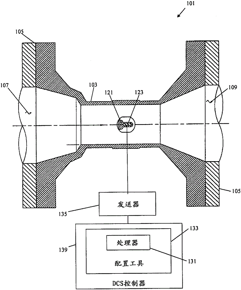
[0019] Referring now to the drawings, first to the attached figure 1 , one embodiment of a vortex flowmeter for measuring fluid velocity, generally designated 101. The vortex flowmeter 101 includes a flow conduit 103 through which fluid flows. Flow conduit 103 is suitably configured to fit within a fluid flow line (not shown). For example, process connections 105 (eg, flanges) are located on opposite ends of the flow conduit 103 for connecting the inlet 107 and outlet 109 of the flow conduit to the respective conduit ends of the pipeline. It is also common in the industry to use so-called wafer connections, so that the flowmeter is installed in the fluid line, and the flow line is adapted to the wafer connection (or any other type of connection, if desired). pieces).

[0020] A bluff body 121 (sometimes referred to in the industry as a swirl remover or strip) is located in the flow conduit 103 . The bluff body 121 is a structure that partially blocks the flow of fluid thro...


PUM


Abstract

A configuration tool is for a vortex flowmeter having a flowtube, a bluff body positioned in the flowtube for shedding vortices in the fluid, and a pressure sensor configured to obtain a signal indicative of a time-varying fluid pressure having an oscillation associated with the vortices. The configuration tool includes a processor that determines a type of fluid flowing through the flowtube based on the amplitude of the oscillation. The processor sets a fluid-type setting of the vortex meter to match the determined type of fluid. An alarming system for a control system including such a flowmeter includes a processor that assesses a density of a fluid flowing through the flowtube based on the amplitude and compares the assessed density to a fluid density configuration setting. The processor activates an alarm if the difference between the assessed density and the fluid density configuration setting exceeds a threshold.

Description

technical field [0001] The present invention generally relates to a vortex flow meter. Background technique [0002] Flow meters measure the flow rate of fluids in pipes or other paths. A fluid may be, for example, a gas or a liquid, and be compressible or incompressible. One type of flowmeter is a vortex flowmeter, and the parameters measured by it include, for example, the flow rate based on the principle of vortex removal. Swirl shedding refers to a natural process of flow through a bluff body (sometimes referred to as an inverted body) causing a boundary layer of slow moving fluid to form along the surface of the bluff body. A region of low pressure is created behind the bluff body and causes the boundary layer to roll up, creating a continuous vortex on the opposite side of the bluff body. The frequency of the vortex is related to the flow rate. Therefore, flow velocity can be measured by detecting eddies. For example, vortices are related to pressure changes in th...

Claims


Application Information

Patent Timeline
IPC IPC(8): G01F1/32
CPCG01F1/3259G01F1/3209
Inventor W·玛特P·阿尔斯特罗姆
Owner INVENSYS SYST INC
Why Eureka
Try Eureka