Optical filter testing method and optical filter testing device

An inspection method and inspection device technology, applied in the field of optical filter inspection, can solve the problems of low efficiency, complexity, and increased defective rate of optical filters, etc.

Inactive Publication Date: 2016-05-11
NANCHANG O FILM OPTICAL ELECTRONICS TECH CO LTD +3
View PDF9 Cites 1 Cited by
  • Summary
  • Abstract
  • Description
  • Claims
  • Application Information

AI Technical Summary

Problems solved by technology

This operation process is very complicated, and the defect rate of the filter will increase after the filter is transferred throu

Method used


Image

  • Optical filter testing method and optical filter testing device
  • Optical filter testing method and optical filter testing device
  • Optical filter testing method and optical filter testing device

Examples


Embodiment Construction

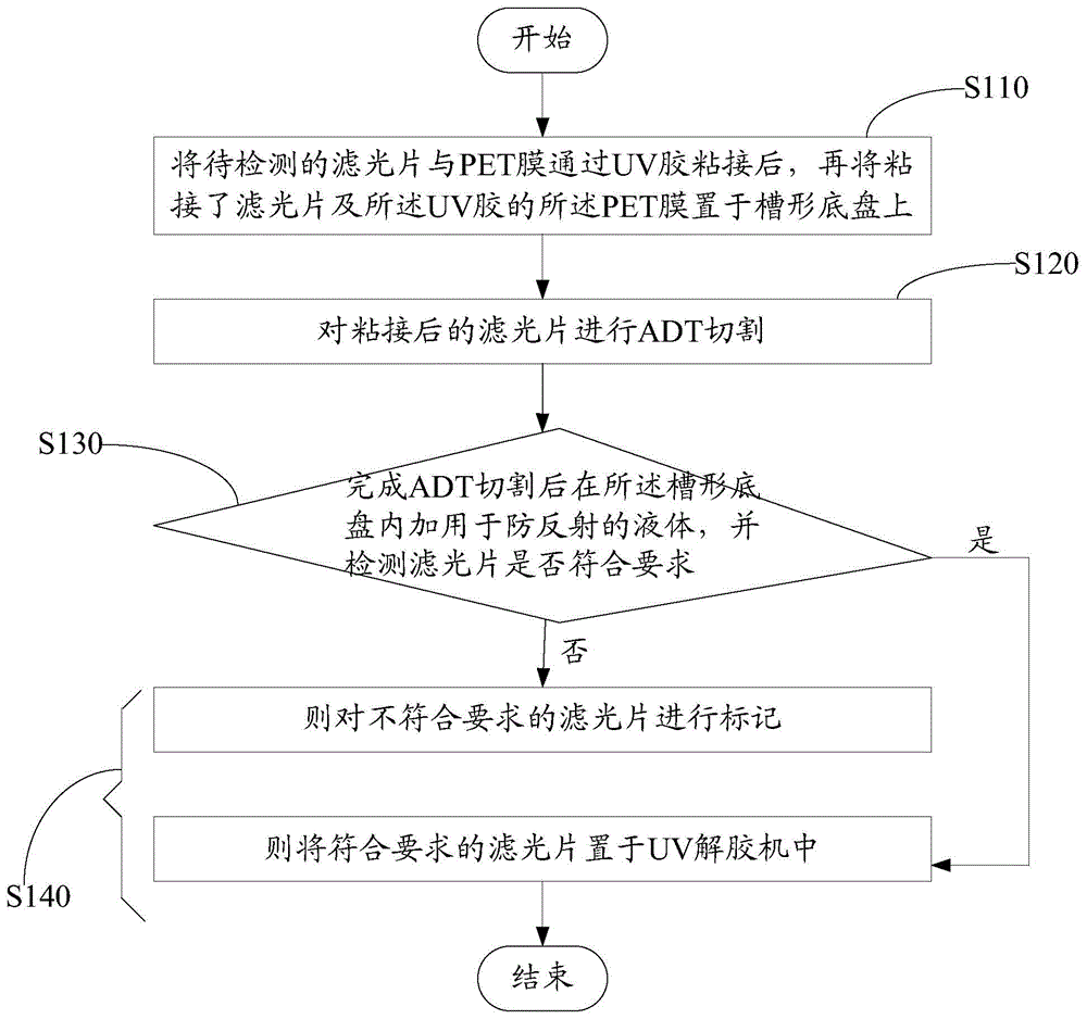
[0026] like figure 1 Shown is the flow chart of the filter inspection method.

[0027] A method for testing an optical filter, comprising the steps of:

[0028] Before the optical filter is bonded, it is also necessary to conduct a routine inspection on the optical filter to be inspected, and the routine inspection is to inspect whether the optical filter has obvious scratches, stains, white spots or chipped edges.

[0029] Visually inspect the appearance of the filter for obvious defects such as scratches, smudges, white spots, or chipped edges. If there is, it will be directly marked as a substandard product. If not, the following tests are performed.

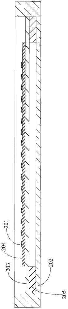
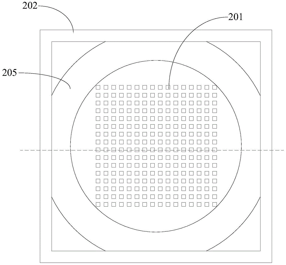
[0030] Step S110, after the optical filter to be detected is bonded to the PET film by UV glue, and then the PET film bonded with the optical filter and the UV glue is placed on a groove-shaped chassis, wherein the PET film The membrane is in contact with the trough pan.

[0031] PET (PolyesterFilm) film is also known as...


PUM


Abstract

An optical filter testing method comprises the steps of after binding an optical filter and a PET film through an UV adhesive, performing ADT cutting; and placing the PET film on which the optical filter and the UV adhesive are bound on a trough-shaped chassis. Therefore, when ADT cutting is performed, the optical filter is placed on the trough-shaped chassis. After cutting is finished, antireflection liquid is added into the trough-shaped chassis, and then whether the optical filter satisfies a requirement is directly tested on the trough-shaped chassis. Therefore, testing position change of the optical filter is not required in the optical filter testing method, number of operation processes is reduced and an optical filter conveying process is saved. Furthermore the invention provides an optical filter testing device.

Description

technical field [0001] The invention relates to optical filter inspection, in particular to an optical filter inspection method and device with simple operation and low cost. Background technique [0002] Filters are widely used in the world of photography. Therefore, it is very important whether the filter meets the requirements in the process of using the filter. In the existing method, after ADT cutting is performed on the optical filter, the cut optical filters are respectively placed in corresponding small grids in a tray with multiple small grids, and then a microscope is used to test whether it meets the requirements. This operation process is very complicated, and the defect rate of the filter will increase after the filter is transferred through the process. Therefore, this inspection method is not only inefficient, but also makes the pass rate of the optical filter low. Contents of the invention [0003] Based on this, it is necessary to provide an inspection ...

Claims


Application Information

Patent Timeline
IPC IPC(8): G01M11/02G01N21/958
Inventor 陈浪赵刚李桂英
Owner NANCHANG O FILM OPTICAL ELECTRONICS TECH CO LTD
Why Eureka
Try Eureka