Electromagnetic Induction Hopkinson Stretch Bar Loading Device and Experimental Method

A technology of electromagnetic induction and loading device, which is applied in the direction of measuring device, using stable tension/pressure test material strength, force/torque/work measuring instrument, etc. Problems such as the inability to unify with the compression loading device

Active Publication Date: 2018-05-15
NORTHWESTERN POLYTECHNICAL UNIV
View PDF6 Cites 0 Cited by
  • Summary
  • Abstract
  • Description
  • Claims
  • Application Information

AI Technical Summary

Problems solved by technology

[0007] In order to overcome the shortcomings in the prior art that the amplitude of the incident wave is difficult to control, the operation is cumbersome, the strain range is limited, some low strain rate experiments cannot be realized, and the tension and compression loading devices cannot be unified, the present invention proposes a Electromagnetic Induction Hopkinson Stretch Bar Loading Device and Experimental Method

Method used


Image

  • Electromagnetic Induction Hopkinson Stretch Bar Loading Device and Experimental Method
  • Electromagnetic Induction Hopkinson Stretch Bar Loading Device and Experimental Method
  • Electromagnetic Induction Hopkinson Stretch Bar Loading Device and Experimental Method

Examples


Embodiment 1

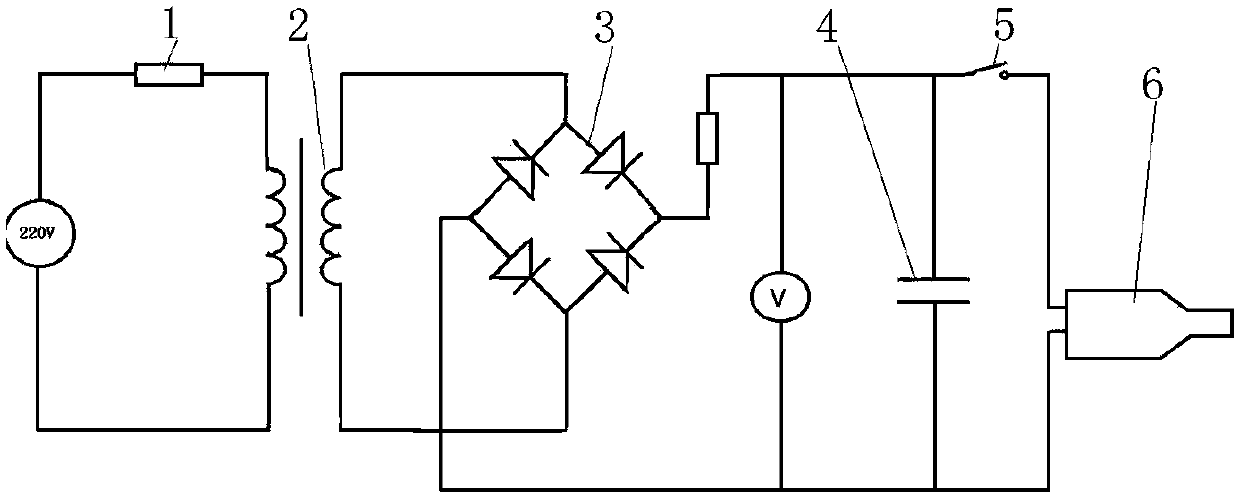
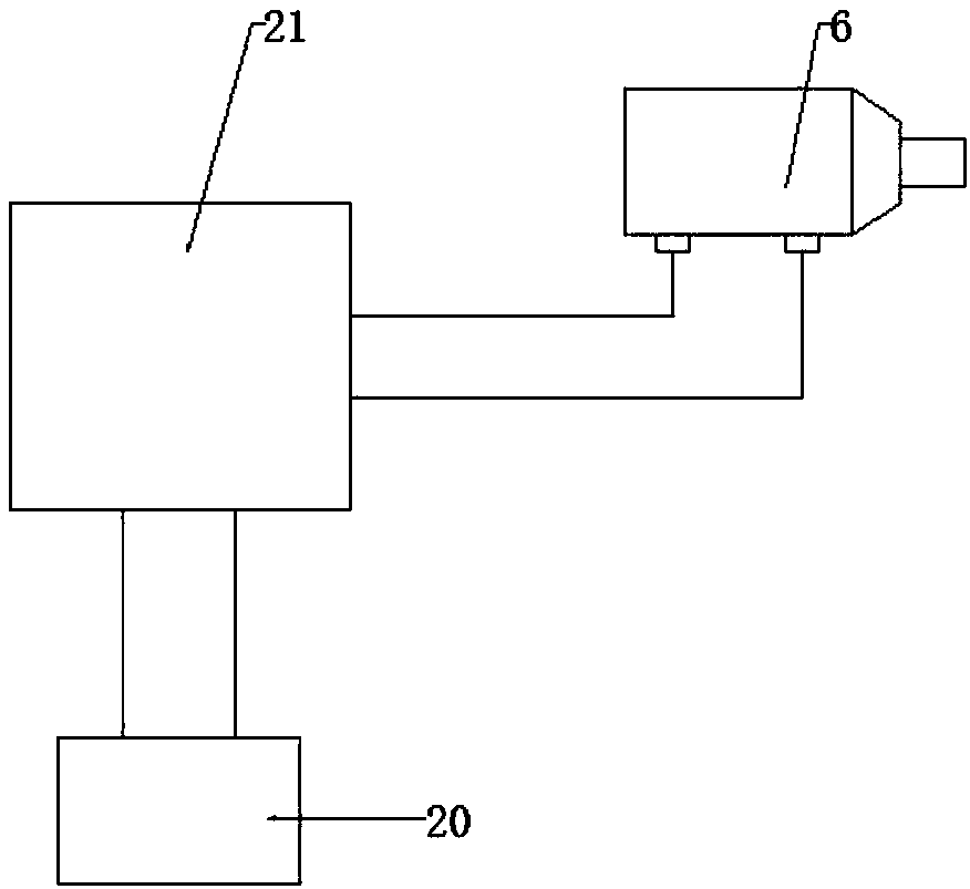
[0057] This embodiment is a Hopkinson stress wave generator based on electromagnetic force, including a power supply 20 , a capacitor charger 21 and a loading gun 6 . The capacitor charger 21 adopts the power supply part of the existing electromagnetic riveting equipment, and the positive output line of the output of the capacitor charger 21 is connected with the positive line of the loading gun 6, and the negative output line is connected with the negative line of the loading gun 6 . The power supply 20 adopts 220V three-phase alternating current.

[0058] In this embodiment, the capacitor charger 21 adopts the power supply part of the electromagnetic riveting equipment disclosed in the patent No. 200520079179. In this embodiment, 10 electrolytic capacitors with a rated voltage of 1000 volts and a rated capacitance of 2000 microfarads are used The capacitor bank is formed in parallel, and the capacitor bank and the electronic switch are installed in the capacitor box, and th...

Embodiment 2

[0091] This embodiment is a Hopkinson stress wave generator based on electromagnetic force, including a power supply 20 , a capacitor charger 21 and a loading gun 6 . The capacitor charger 21 adopts the power supply part of the existing electromagnetic riveting equipment, and the positive output line of the output of the capacitor charger 21 is connected with the positive line of the loading gun 6, and the negative output line is connected with the negative line of the loading gun 6 . The power supply 20 adopts 220V three-phase alternating current.

[0092] In this embodiment, the capacitor charger 21 adopts the power supply part of the electromagnetic riveting equipment disclosed in the patent No. 200520079179. In this embodiment, 10 electrolytic capacitors with a rated voltage of 1000 volts and a rated capacitance of 2000 microfarads are used The capacitor bank is formed in parallel, and the capacitor bank and the electronic switch are installed in the capacitor box, and th...


PUM

PropertyMeasurementUnit
lengthaaaaaaaaaa

Abstract

An electromagnetic induction type Hopkinson tension bar loading device and experimental method, the positive output line of the output of the capacitor charger is connected to the positive line of the loading gun, the negative output line is connected to the negative line of the loading gun, and the electric The principle of magnetic induction can generate both compressive stress waves and tensile stress waves, and is applied to the loading of Hopkinson tension rods and compression rods. The loading system of the Hopkinson tension rod and compression rod can simultaneously realize the strain rate and strain range that cannot be achieved by the traditional separate Hopkinson rod experiment on the same device, standardize the Hopkinson rod experiment technology, and make the tension rod and compression rod The experimental device of the compression rod is integrated, which saves the complexity of the equipment and the occupied space.

Description

technical field [0001] The present invention relates to a stress wave generating device and method for testing dynamic mechanical properties of materials, in particular to a stress wave generating device and method based on electromagnetic force. input device. Background technique [0002] At present, in the field of material science, the most widely used methods for measuring the mechanical properties of materials under high strain rates are split Hopkinson compression rod technology and tension rod technology. The basic principle of this method is: place a short sample between two tension rods or compression rods, and input a tensile stress wave or a compressive stress wave to the incident rod in a certain way to load the sample. Simultaneously, the pulse signal is recorded by using the strain gauge glued on the tie rod or the pressure rod at a certain distance from the end of the rod. If the tension or compression rod remains elastic, the pulses in the rod will propagat...

Claims


Application Information

Patent Timeline
Patent Type & Authority Patents(China)
IPC IPC(8): G01N3/317
CPCG01N3/317G01N2203/001G01N3/04G01N2203/0098G01N2203/0252G01N3/08G01N2203/0017G01N2203/0019G01N2203/005G01L5/00
Inventor 李玉龙聂海亮索涛汤忠斌
Owner NORTHWESTERN POLYTECHNICAL UNIV
Why Eureka
Try Eureka