Gain and direction oriented large-scale deformed paraboloid antenna panel fit rotation adjusting method

A parabolic antenna, rotation adjustment technology, applied in the direction of antennas, electrical components, etc., can solve the problems of inability to meet the performance compensation of large antennas, the inability to compensate for the loss of antenna gain, and the cumbersome adjustment process.

Active Publication Date: 2016-05-11
XIDIAN UNIV
View PDF3 Cites 8 Cited by
  • Summary
  • Abstract
  • Description
  • Claims
  • Application Information

AI Technical Summary

Problems solved by technology

Among the existing patents related to the electrical performance compensation of large antennas, such as the patent of the Key Laboratory of Electronic Equipment Structural Design of the Ministry of Education of Xidian University "A Method of Feed Position Compensation for Deformed Large Single Reflector Antenna", " A Subsurface Compensation Method for a Large Shaped Double-Reflector Antenna Based on Electromechanical Coupling" and "A Direction Adjustment Method for a Large-scale Shaped Double-Reflector Antenna Based on Electromechanical Coupling" are both based on the traditional antenna

Method used


Image

  • Gain and direction oriented large-scale deformed paraboloid antenna panel fit rotation adjusting method
  • Gain and direction oriented large-scale deformed paraboloid antenna panel fit rotation adjusting method
  • Gain and direction oriented large-scale deformed paraboloid antenna panel fit rotation adjusting method

Examples


Embodiment Construction

[0064] The present invention will be further described below in conjunction with the accompanying drawings and embodiments.

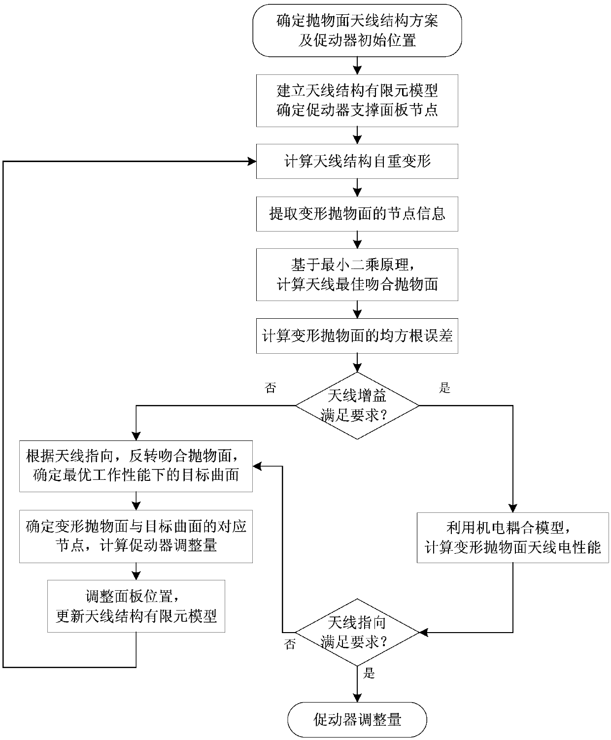
[0065] Such as figure 1 As shown, a method for coincident rotation adjustment of the face gain and pointing large-scale deformed parabolic antenna panel, the specific steps are as follows:

[0066] Step 1. Determine the structure scheme of the parabolic antenna and the initial position of the actuator, establish the finite element model of the antenna structure, and determine the supporting panel nodes of the actuator

[0067] According to the structural parameters, operating frequency and material properties of the large parabolic antenna, determine the antenna structure scheme and the initial position of the actuator, establish the finite element model of the antenna structure under ideal conditions in the finite element mechanical analysis software, and determine the actuator support panel node; where the structural parameters of the large parabolic...


PUM


Abstract

The invention discloses a gain and direction oriented large-scale deformed paraboloid antenna panel fit rotation adjusting method. The method comprises following steps: determining the structure scheme of a paraboloid antenna and the initial position of an actuator; building a finite element model and the supporting panel nodes of the actuator; calculating the self-weight deformation of an antenna structure and extracting deformed paraboloid nodes; calculating the optimum fit paraboloid of the antenna; calculating the root-mean-square error of the deformed paraboloid and judging whether antenna gain satisfies a demand; reversing the fit paraboloid and determining a target curve under optimum working performance; determining the corresponding nodes of the deformed paraboloid and the target curve and calculating the adjusting quantity of the actuator; adjusting the position of the panel, updating the finite element model of the antenna structure, calculating the electric performance of the deformed antenna by an electromechanical coupling model, judging whether the antenna direction satisfies a demand, outputting the adjusting quantity of the actuator, and obtaining the optimum panel fit rotation adjusting quantity. The method of the invention is advantaged by that the total travel of the actuator is short, the precision of the reflection surface of the antenna is clearly improved, the antenna gain is improved, and the working direction of the antenna is ensured.

Description

technical field [0001] The invention belongs to the technical field of antennas, and in particular relates to a gain-oriented and directing-oriented large-scale deformed parabolic antenna panel matching rotation adjustment method, which is used to actively adjust the position of the reflective surface panel of the large-scale deformed parabolic antenna to optimize the antenna's working performance. Background technique [0002] A large-area area antenna mainly used for receiving functions must be built both large and well. "Big" means that it has a large aperture and a large gathering area, which can receive stronger signals and observe weak sources in space; "good" means There are two aspects, one is to have a more accurate reflector surface, so that the antenna can be observed in a shorter wave band, and the other is to have a higher pointing accuracy, to achieve narrow beam observation to obtain higher resolution, so as to realize the radio telescope "seeing Far, see clea...

Claims


Application Information

Patent Timeline
IPC IPC(8): H01Q19/10H01Q15/14H01Q15/16
CPCH01Q15/14H01Q15/16H01Q19/10
Inventor 王从思肖岚杜敬利王伟保宏王艳连培园段宝岩黄进王娜唐宝富王猛
Owner XIDIAN UNIV
Why Eureka
Try Eureka