Battery system

A battery system and battery technology, applied in the direction of secondary batteries, battery overcharge protection, battery disconnection circuit, etc., can solve the problem of increasing the battery voltage above the upper limit

Inactive Publication Date: 2016-05-11
TOYOTA JIDOSHA KK
View PDF10 Cites 10 Cited by
  • Summary
  • Abstract
  • Description
  • Claims
  • Application Information

AI Technical Summary

Problems solved by technology

Depending on the SOC of the battery, the voltage value of the battery may...

Method used


Image

  • Battery system
  • Battery system
  • Battery system

Examples


Embodiment 1

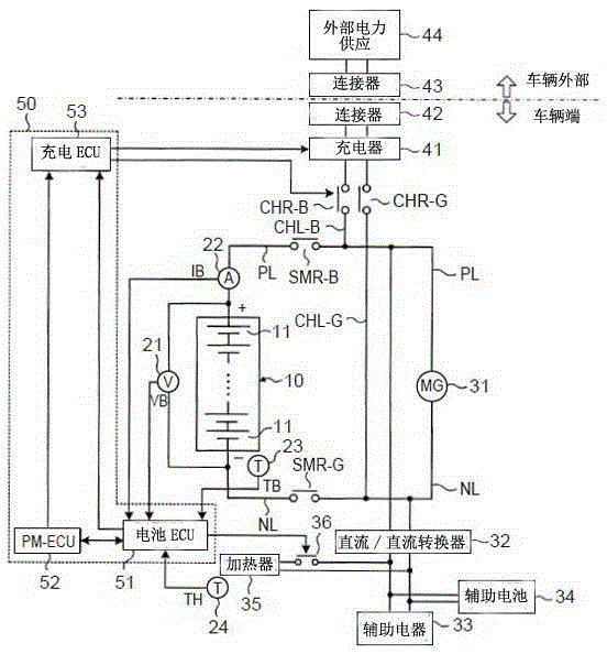
[0030] figure 1 It is a schematic structural diagram of the battery system of this embodiment. figure 1 The battery system shown is installed on a vehicle.

[0031] The main battery 10 has a plurality of unit cells 11 connected in series. As the unit battery 11 , for example, a secondary battery such as a nickel hydrogen battery or a lithium ion battery can be used. The main battery 10 may include a plurality of unit cells 11 connected in parallel.

[0032] figure 1 The illustrated battery system is controlled by an ECU (Electronic Control Unit) 50 . The ECU 50 described here is configured to include a battery ECU 51 , a power management ECU (PM-ECU) 52 , and a charging ECU 53 . The ECU 50 corresponds to the controller of the present invention.

[0033] Voltage sensor 21 detects voltage value VB of main battery 10 and outputs the detection result to battery ECU 51 . The current sensor 22 detects the current value IB of the main battery 10 and outputs the detection resul...

Embodiment 2

[0096] Embodiment 2 of the present invention will be described below. In this embodiment, differences from Embodiment 1 are mainly described.

[0097] In Embodiment 1, in the case where power is supplied to the heater 35 after the SOC of the main battery 10 reaches the threshold SOC_th, power is not supplied to the main battery 10 . On the other hand, in the present embodiment, after the SOC of the main battery 10 reaches the threshold SOC_th, electric power is supplied to the heater 35 , and by supplying electric power to the main battery 10 , also The constant current and constant voltage charging.

[0098] The external charging process in this embodiment will combine Figure 8 The flow chart shown is described. Figure 8 equivalent to Figure 4 , and with Figure 4 Processes that are the same as those described are denoted by the same reference numerals. exist Figure 8 In the flow shown, with Figure 4 Where the flow shown differs will be mainly described below.

...

Embodiment 3

[0109] Embodiment 3 of the present invention will be described below. In this embodiment, differences from Embodiment 2 are mainly described.

[0110] In Embodiment 2, constant current charging is performed with electric power α until the SOC of the main battery 10 reaches the threshold SOC_th. In this embodiment, the charging power during constant current charging is weakened before the SOC of the main battery 10 reaches the threshold SOC_th. Then, after the SOC of the main battery 10 reaches the threshold SOC_th, similar to Embodiment 2, constant current and constant voltage charging is performed by supplying power to the main battery 10 regardless of whether power is supplied to the heater device 35.

[0111] The flow of external charging in this embodiment will be set Figure 10 and Figure 11 The flow chart in is described. Figure 10 and Figure 11 equivalent to Figure 8 .

[0112] In step S401 , the battery ECU 51 calculates the SOC of the main battery 10 and d...


PUM


Abstract

A battery system includes: a battery configured to be charged or discharged; a temperature sensor configured to detect a temperature of the battery; a heater configured to warm the battery; a charger configured to supply electric power from an external power supply to the battery and the heater; a relay provided in a passage through which the electric power from the charger is supplied to the battery; and a controller configured to control operations of the charger and the relay. The controller is configured to supply predetermined electric power from the charger to the heater and turn off the relay so as not to supply the electric power from the charger to the battery in a case where an SOC of the battery is equal to or more than a threshold and the temperature of the battery is lower than a predetermined temperature.

Description

technical field [0001] The present invention relates to a battery system including: a battery charged with electric power from an external power source; and a heater for warming up the battery by receiving electric power from the external power source. Background technique [0002] In Japanese Patent Application Publication No. 2012-191782 (JP 2012-191782A), power (charging power) of a charger connected to an external power source is supplied to the battery to charge the battery. In addition, electric power from the charger is supplied to the heater to generate heat in the heater, thereby warming up the battery. [0003] When power from the charger is supplied to the heater and the battery, power that should be supplied to the heater is supplied to the battery with power supply to the heater cut off. Even in the case of attempting to reduce the charging power of the battery in this state, the charging power of the battery temporarily increases for a period of time from when...

Claims


Application Information

Patent Timeline
IPC IPC(8): H02J7/00B60L11/18H01M10/615H01M10/625H01M10/635H01M10/657
CPCH02J7/0031B60L1/02B60L2240/545Y02T10/7072Y02T90/14B60L53/14B60L58/27H02J7/00302B60L58/15Y02T10/70H02J7/0042
Inventor 村田崇
Owner TOYOTA JIDOSHA KK
Why Eureka
Try Eureka