
DC power supply redundancy system

A technology of DC power supply and backup power supply, which is applied in the direction of emergency power supply arrangements, collectors, electric vehicles, etc., can solve the problems of reducing the power supply effect of battery devices, and achieve the effect of improving power supply effect and reducing line loss

Active Publication Date: 2016-05-11
ACBEL POLYTECH INC
View PDF5 Cites 12 Cited by
  • Summary
  • Abstract
  • Description
  • Claims
  • Application Information

AI Technical Summary

Problems solved by technology

[0004] However, since the working voltage of the electronic equipment is low voltage, generally 12V, the DC voltage provided by the battery device is low voltage. If the output power of the battery device is P, according to the electric power work formula: P=IV, I is the battery device The output current of the battery device, V is the output voltage of the battery device, because the output voltage V of the battery device is inversely proportional to the output current I, so the output current I will be increased under the low voltage condition
In this way, if the line impedance between the battery device and the electronic equipment is expressed as RLINE, RLINE is a constant, and the line loss between the battery device and the electronic equipment is expressed as PLOSS, then PLOSS=I2×RLINE, it can be seen that the larger The output current I will increase the line loss PLOSS, thereby reducing the power supply effect of the battery device

Method used


Image

  • DC power supply redundancy system
  • DC power supply redundancy system
  • DC power supply redundancy system

Examples


Embodiment Construction

[0048] Below in conjunction with accompanying drawing, structural principle and working principle of the present invention are specifically described:

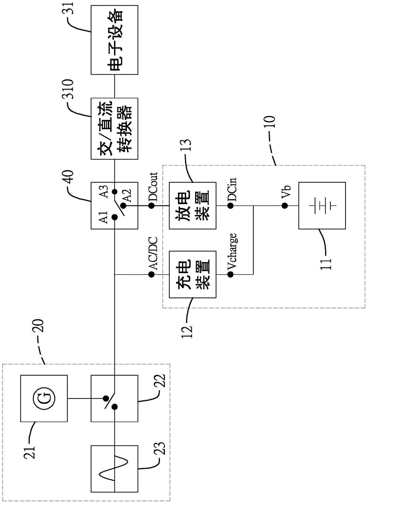
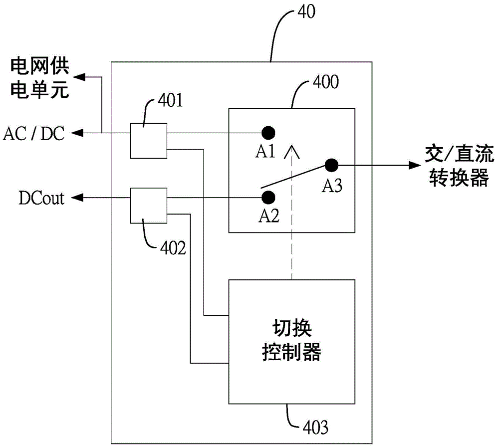
[0049] Please refer to figure 1 The shown DC power backup system of the present invention is used to connect a grid power supply unit 20 and at least one AC / DC converter 310. The DC power backup system of the present invention includes at least one DC power backup module 10 and at least one An automatic transfer switch element (Automatic TransferSwitch, ATS) 40 .

[0050] The AC / DC converter 310 includes an AC input terminal and a DC output terminal, and its DC output terminal is used to connect an electronic device 31. The electronic device 31 is a DC load. The AC / DC converter 310 can be a power supply ( powersupply). The AC / DC converter 310 needs to receive a power supply greater than a minimum operating voltage (at least 90 volts) of the AC / DC converter 310 at its AC input terminal, so that the AC / DC converter 310 can wor...


PUM


Abstract

A DC power supply redundancy system comprises an automatic switching component and a DC redundancy module. The automatic switching component comprises a first power input end, a second power input end and a power output end. The first power input end is connected with a power-grid power supply unit. The power output end is connected with one AC input end of an AC / DC converter. One DC output end of the DC redundancy module is connected with the second power input end of the automatic switching component. When power supply of the power-grid power supply unit is abnormal, the power output end of the automatic switching component is switched for connecting with the second power input end, thereby supplying a DC redundancy power to the AC / DC converter by the DC redundancy module, wherein the voltage of the DC redundancy power is higher than the lowest working voltage of the AC / DC converter.

Description

technical field [0001] The invention relates to a power source backup system, in particular to a DC power source backup system. Background technique [0002] A power supply is a voltage conversion device that converts AC power into DC power. Its input is connected to the mains grid to receive an AC power, and its output is connected to the power input of an electronic device. The power supply is the After the AC power is converted into a DC power, the DC power is output to the electronic device as a working power source for the electronic device. [0003] Electronic devices such as network servers and cloud hard disks are connected to the network during operation and often transmit important data, so these electronic devices have high power requirements. However, there is uncertainty about whether the mains power grid can provide stable power supply. If the power company repairs power generation equipment, has no warning or unexpected power outage, these electronic devices ...

Claims


Application Information

Patent Timeline
Patent Type & Authority Applications(China)
IPC IPC(8): H02J9/06H02J7/00H02J7/02
Inventor 叶家安林维亮彭崑展
Owner ACBEL POLYTECH INC
Learn More