Eureka AIR delivers breakthrough ideas for toughest innovation challenges, trusted by R&D personnel around the world.

Power supply for supplying power to a lamp

Inactive Publication Date: 2009-03-05
DELTA ELECTRONICS INC
View PDF5 Cites 8 Cited by
  • Summary
  • Abstract
  • Description
  • Claims
  • Application Information

AI Technical Summary

Benefits of technology

[0012]The primary objective of this invention is to provide a power supply comprising a dimming circuit for dimming a lamp. The dimming circuit is configured to gradually decrease output current from a power supply to a lamp when dimming, and turn off the power supply when a frequency of the output current exceeds a pre-determined value. As a result, a dimming function is accomplished and the service life of the lamp is prolonged.
[0013]Another objective of this invention is to provide a power supply with an over-current control circuit being configured to turns off the power supply when an over-current signal represents abnormal statuses such as open-circuited status, short-circuited status, or arcing status. Thus, a surge current induced by the abnormal statuses may be eliminated to prevent the power supply from being damaged.
[0014]Another objective of this invention is to provide a power supply with a high-frequency current detection circuit. The power supply comprises a current output module configured to provide a current to a high-voltage load; the high-frequency current detection circuit is configured to detect whether a current supplied to the high-voltage load is a high-frequency current to prevent damage to the electronic elements in the high-voltage load. To this end, the high-frequency current detection circuit comprises a first capacitive element, a resistor and a second capacitive element.
[0015]Yet an objective of this invention is to provide a power supply with a current adjusting circuit for adjusting an alternating current outputted to a lamp set in response to an environment temperature to supply an adequate alternating current at a low temperature for starting the lamp set. More particularly, according to the present invention, the alternating current is increased at a low temperature to increase the cross voltage of the capacitor (i.e., a passive element in series) connected in series with the lamps, so that the lamps that would otherwise fail to start will obtain an increased starting voltage and light up. In this way, it is possible to start a plurality of lamps, connected in parallel, simultaneously with a single transformer at a low temperature.

Problems solved by technology

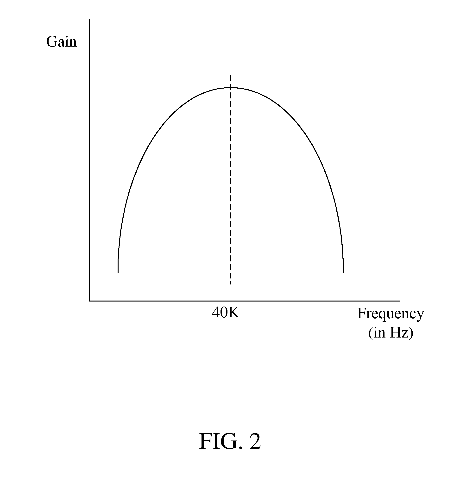
Besides the range, either an excessively high or an excessively low frequency of the AC power supply would result in increased impedance, i.e. a decreased gain, of the lamp.
However, when dimming a lamp with the above methods, there is still energy outputting to the lamp.
Since the service life of the lamp is positively related to the illumination duration of the lamp, and the purpose of dimming the lamp is to decrease the output brightness of the lamp, the energy output continued during the dimming process may not only unnecessarily consume electric power, but also shorten service life of the lamp.
Also, the power supply may suffer surge current when open-circuited status, short-circuited status, or arcing status occurs.
If the power supply cannot turns off timely when the aforementioned statuses occur, the lamp or the power supply may be damaged by the surge current.
The arc is essentially a high-frequency current, which may damage the electronic elements of an electrical product and may further lead to the complete failure of the product.
However, lamps are known to require a larger starting current at a lower environment temperature.
Therefore, if the power supply module still supplies a fixed alternating current when the lamps are exposed to a much lower environment temperature, some of the lamps may fail to start.

Method used


Image

  • Power supply for supplying power to a lamp
  • Power supply for supplying power to a lamp
  • Power supply for supplying power to a lamp

Examples


Embodiment Construction

[0024]This invention relates to a power supply for supplying power to a lamp with functions of dimming, over-current protection, over-voltage protection, arcing protection, and low-temperature start-up. Embodiments will be described hereinbelow to explain this invention. However, these embodiments are not intended to limit that this invention can only be embodied in any specific context, applications or with particular methods described in these embodiments. Therefore, description of the embodiments is only intended to illustrate this invention, rather than to limit this invention. It should be noted that, in the following embodiments and attached drawings, elements not directly related to this invention are omitted from depiction, and the dimensional relationships among various elements are slightly exaggerated for ease of understanding.

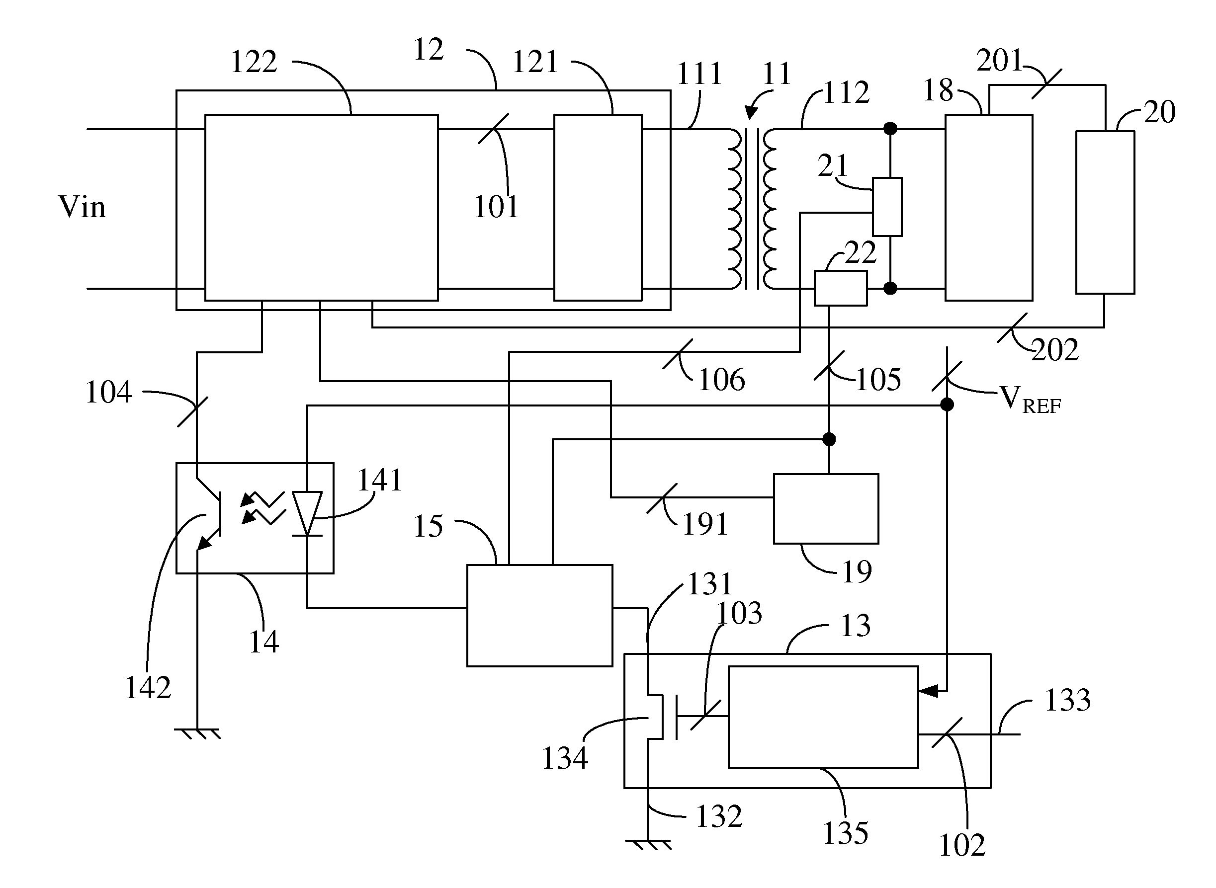
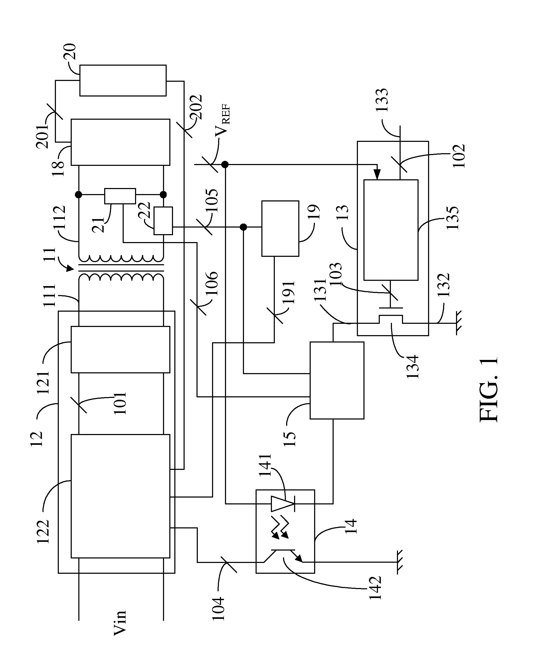
[0025]FIG. 1 is a block diagram of a power supply comprising a dimming circuit. The power supply is configured to receive a DC power input Vin and ...


PUM


Abstract

A power supply for supplying power to a lamp with functions of dimming, over-current protection, over-voltage protection, arcing protection, and low-temperature start-up is provided. When frequency of the output current exceeds a predetermined value, the power supply is turned off to accomplish a dimming goal and extend lifetime of the lamp. When abnormal statuses such as open-circuited status, short-circuited status, or arcing status occur, a surge current induced by the abnormal statuses may be eliminated to prevent the power supply from being damaged. A high-frequency current detection circuit is configured to detect whether a current supplied to the high-voltage load is a high-frequency current to prevent damage to the electronic elements in the high-voltage load. A current adjusting circuit is configured to adjust an alternating current outputted to a lamp set in response to an environment temperature to supply an adequate alternating current at a low temperature for starting the lamp set.

Description

CROSS-REFERENCE TO RELATED APPLICATIONS[0001]This application claims priority to Taiwan Patent Application No. 096132331, filed on Aug. 30, 2007, Taiwan Patent Application No. 096135349, filed on Sep. 21, 2007, Taiwan Patent Application No. 096139818, filed on Oct. 24, 2007, Taiwan Patent Application No. 096143207, filed on Nov. 15, 2007, and Taiwan Patent Application No. 097112847, filed on Apr. 9, 2008, the disclosures of which are incorporated herein by reference in their entirety.BACKGROUND OF THE INVENTION[0002]1. Field of the Invention[0003]The present invention relates to a power supply. More particularly, the present invention relates to a power supply for supplying power to a lamp with functions of dimming, over-current protection, over-voltage protection, arcing protection, and low-temperature start-up.[0004]2. Descriptions of the Related Art[0005]Nowadays, lighting has become indispensable to people's life, and commonly using for lighting are still lamps. Generally, in or...

Claims


Application Information

Patent Timeline
IPC IPC(8): H05B41/24H05B41/36H02H3/02
CPCH05B41/3921
Inventor CHANG, SHIH-HSIENHSIEH, MING-CHIHLEE, HONG-CHIHHUANG, YAO-TIEN
Owner DELTA ELECTRONICS INC
Why Eureka
Eureka Blog
Learn More