Pivoting fitting

A technology of pivoting and pivoting movement, which is applied in the directions of pivot connection, transportation and packaging, and the special position of the vehicle, which can solve the problems of large locking noise and troubles, and achieve the reduction of locking noise, reduction of noise development, Effect of Ensuring Functional Reliability

Active Publication Date: 2016-05-11
HETTICH FRANKE
View PDF7 Cites 2 Cited by
  • Summary
  • Abstract
  • Description
  • Claims
  • Application Information

AI Technical Summary

Problems solved by technology

The disadvantage of this pivoting device is that the locking of the pawl takes place in a relatively loud manner, since the metal spring presses the pawl against the toothed part with high force, thus generating a loud locking noise during the pivoting of the leaf assembly, resulting in troubled

Method used


Image

  • Pivoting fitting
  • Pivoting fitting
  • Pivoting fitting

Examples


Embodiment Construction

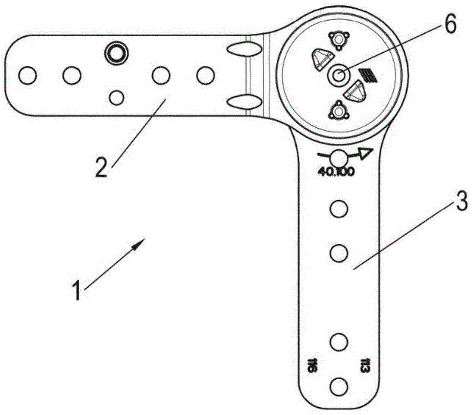
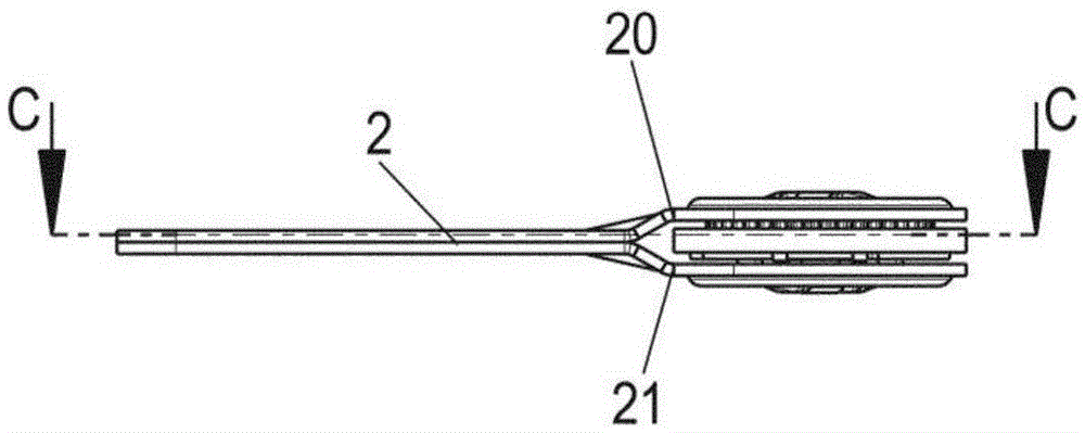
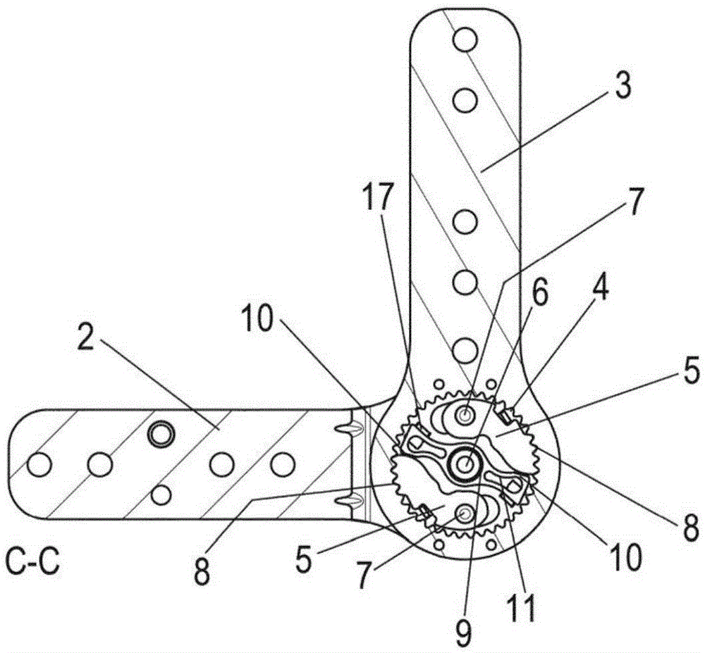
[0020] The pivoting device 1 comprises a first sheet assembly 2 and a second sheet assembly 3 which are pivotable relative to each other about an axis 6 . The first blade pack 2 comprises a first part 20 and a second part 21 which are connected to each other on a portion projecting radially from the shaft 6 and surround the central region of the second blade pack 3 in the region of the shaft 6 . In the intermediate area between the first part 20 and the second part 21 there is provided a locking or locking mechanism which allows movement of the first sheet assembly 2 relative to the second sheet assembly 3 in a first direction and in a second limited in direction. The restraint is disengaged in the end position and the sheet assemblies 2 and 3 can be moved back to the initial position.

[0021] like Figure 1C As shown, the locking mechanism comprises two pawls 5 mounted for rotation about an axis 7 . Two shafts 7 are provided spaced apart from the central shaft 6 for pivot...


PUM


Abstract

A pivoting fitting (1) comprises a first tab (2) and a second tab (3) which are mounted so as to be rotatable relative to each other about an axis (6), and a locking mechanism having at least one pawl (5) and toothing (4), wherein the pawl (5) can be engaged in the toothing in a plurality of positions and permits a pivoting movement of the first tab (2) with respect to the second tab (3) in a first direction and blocks movement in an opposing direction, and wherein at least one control element (14) is provided to disengage the at least one pawl (5) from the toothing (4) and then to pivot the first tab (2) with respect to the second tab (3) in the second direction through an angle, wherein the at least one pawl (5) is retained by a spring element (9) in a position engaged in the toothing (4), wherein the spring element (9) is at least partially made from an elastomer material. In this way, the pivoting fitting (1) can be pivoted with little noise.

Description

technical field [0001] The invention relates to a pivot device having the features of claim 1 . Background technique [0002] Patent EP1284447 discloses a pivoting device wherein a first sheet assembly is pivotable relative to a second sheet assembly, wherein the sheet assemblies can be mutually held in a predetermined angular position by a locking or locking mechanism. The locking mechanism comprises two pawls which are pivotally mounted and engaged with toothed members via spring elements. A metal spring element presses the pawl into the tooth joint and can be forced to disengage the pawl from the tooth joint via the cam disc and then pivot the leaf pack to the initial position. The disadvantage of this pivoting device is that the locking of the pawl takes place in a relatively loud manner, since the metal spring presses the pawl against the toothed part with high force, thus generating a loud locking noise during the pivoting of the leaf assembly, resulting in troubled....

Claims


Application Information

Patent Timeline
Patent Type & Authority Applications(China)
IPC IPC(8): A47C1/026
CPCA47C1/026A47C7/54A47C7/38B60N2/235F16C11/10
Inventor E·豪格G·施特劳斯S·格拉斯沃尔
Owner HETTICH FRANKE
Why Eureka
Try Eureka