
Adsorption mechanism

A technology of adsorption mechanism and adsorption surface, applied in the direction of workpiece clamping device, manufacturing tools, etc., can solve the problems of increasing production costs, etc., and achieve the effect of wide application and simple operation

Inactive Publication Date: 2016-05-18
FU DING ELECTRONICSAL TECH JIASHAN +2
View PDF5 Cites 19 Cited by
  • Summary
  • Abstract
  • Description
  • Claims
  • Application Information

AI Technical Summary

Problems solved by technology

[0002] In the process of processing, it is usually necessary to position the workpiece to be processed on the processing platform. The traditional mechanical clamping method is difficult to effectively ensure the flatness of some workpieces, for example, flat plate structure workpieces, so a vacuum adsorption mechanism appears. The vacuum adsorption mechanism relies on the generated vacuum adsorption force to adsorb and position the workpiece, which effectively solves the problem that the traditional mechanical clamping mechanism cannot solve. However, with the development of technology, there are more and more types of products, and the sizes of the products are also different. The adsorption fixtures cannot meet the adsorption and positioning of products of different sizes at the same time, so it is necessary to develop different adsorption and positioning fixtures for different products, which increases the production cost

Method used


Image

  • Adsorption mechanism
  • Adsorption mechanism
  • Adsorption mechanism

Examples


Embodiment Construction

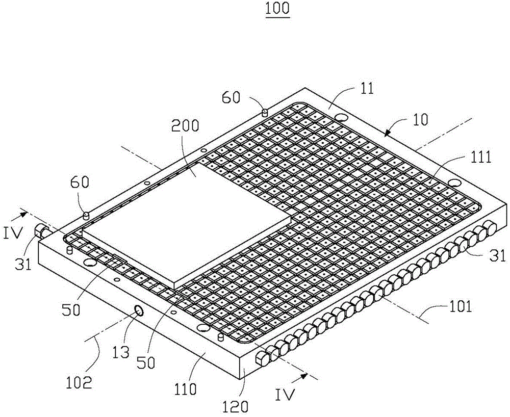
[0014] see figure 1 , the adsorption mechanism 100 of the embodiment of the present invention is used to adsorb and position the workpiece 200 for processing. In this embodiment, the workpiece 200 is an aluminum alloy plate.

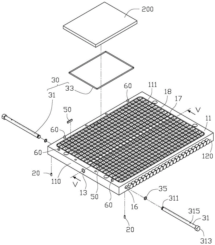
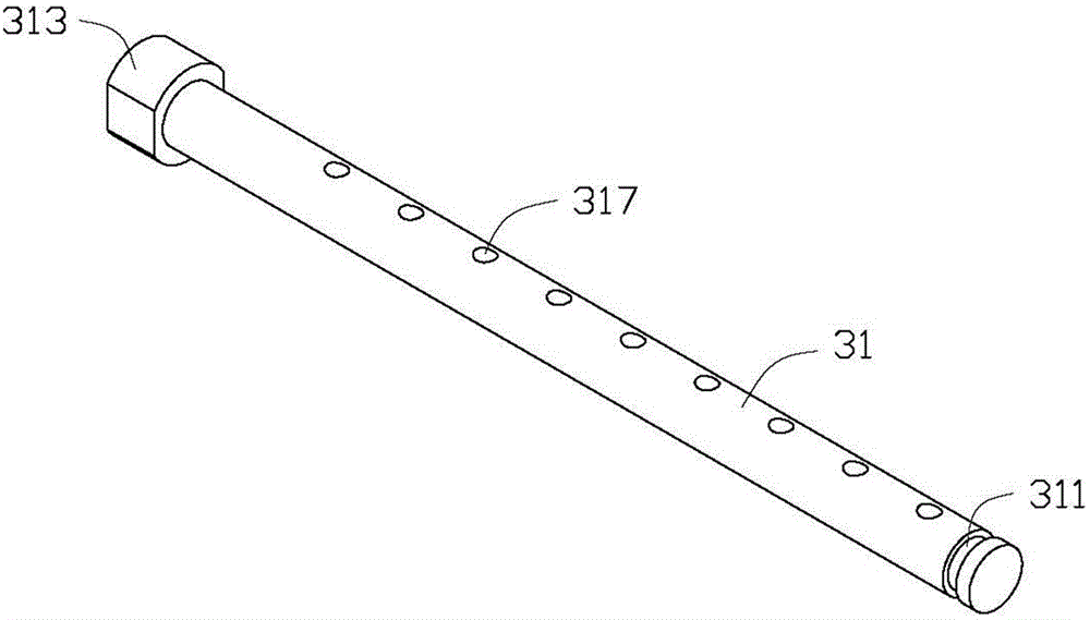
[0015] Please also see figure 2 and image 3 , the adsorption mechanism 100 includes a base body 10 , a control member 30 and a positioning member 50 installed on the base body 10 .

[0016] Please also see image 3 and Figure 5 , the base body 10 is roughly in the shape of a rectangular block, which includes an adsorption surface 11 , two opposite first side surfaces 110 and two opposite second side surfaces 120 . The first side 110 is disposed on opposite sides parallel to the transverse axis 101 of the first base 10 , and the second side 120 is disposed on both sides parallel to the longitudinal axis 102 of the base 10 . The adsorption surface 11 is perpendicular to the first side 110 and the second side 120 . A plurality of suction holes 111...


PUM


Abstract

The invention discloses an adsorption mechanism. The adsorption mechanism is used for adsorbing to position workpieces and comprises a substrate, wherein the substrate is used for placing workpieces; the substrate comprises an adsorption surface in which a plurality of air suction holes are formed; an air duct runs through the interior of the substrate; the air duct penetrates through at least one side surface of the substrate to form a main air hole; the main air hole is used for being connected with an external vacuum device so that the air duct can present negative pressure; a plurality of holding holes alternately run through the side surface of the substrate; each holding hole is communicated with a corresponding air suction hole in the adsorption surface; and the plurality of holding holes are communicated with the air duct; the adsorption mechanism furthermore comprises operating rods which are correspondingly held in the holding holes; the operating rods are capable of moving along the holding holes; and at the positions of the holding holes, the operating rods are capable of blocking the communication between the corresponding air suction holes and the air duct.

Description

technical field [0001] The invention relates to an adsorption mechanism, in particular to an adsorption positioning device applicable to workpieces of different sizes. Background technique [0002] In the process of processing, it is usually necessary to position the workpiece to be processed on the processing platform. The traditional mechanical clamping method is difficult to effectively ensure the flatness of some workpieces, for example, flat plate structure workpieces, so a vacuum adsorption mechanism appears. The vacuum adsorption mechanism relies on the generated vacuum adsorption force to adsorb and position the workpiece, which effectively solves the problem that the traditional mechanical clamping mechanism cannot solve. However, with the development of technology, there are more and more types of products, and the sizes of the products are also different. Advanced adsorption fixtures cannot satisfy the adsorption and positioning of products of different sizes at t...

Claims


Application Information

Patent Timeline
Patent Type & Authority Applications(China)
IPC IPC(8): B25B11/00
Inventor 罗海良刘德兵
Owner FU DING ELECTRONICSAL TECH JIASHAN
Learn More