Manufacturing and assembling method for variable-rigidity traction rubber pile and rigidity varying method

An assembly method and variable stiffness technology, which is applied in the field of rolling stock vibration reduction, can solve problems such as increased stiffness and low stiffness, and achieve the effects of reducing wear, reducing maintenance costs, and making assembly simple and convenient

Inactive Publication Date: 2016-05-18
ZHUZHOU TIMES NEW MATERIALS TECH
View PDF10 Cites 12 Cited by
  • Summary
  • Abstract
  • Description
  • Claims
  • Application Information

AI Technical Summary

Problems solved by technology

[0015] The object of the present invention is to address the deficiencies of the existing traction rubber piles, to provide a method for making and assembli...

Method used


Image

  • Manufacturing and assembling method for variable-rigidity traction rubber pile and rigidity varying method
  • Manufacturing and assembling method for variable-rigidity traction rubber pile and rigidity varying method
  • Manufacturing and assembling method for variable-rigidity traction rubber pile and rigidity varying method

Examples


Embodiment 1

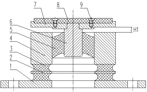
[0053] Such as figure 2 As shown, a variable stiffness traction rubber pile production and assembly method uses a special mold to vulcanize and bond the metal bottom plate 1 and the metal partition 2 through the bottom elastic rubber body 3, and the metal partition 2 and the metal jacket 4 pass through the bottom elastic The rubber body 3 is bonded together, the metal outer casing 4 and the metal inner casing 6 are vulcanized and bonded together through the upper elastic rubber body 5, the wear-resistant plate 8 and the metal top plate 7 are connected together by fastening screws 9, and the metal top plate 7 is passed through Ying fit is connected together with metal inner sleeve 6 tops. When the rubber stopper is loaded, the elastic rubber body 5 is deformed, the interval H1 of the gap section is gradually reduced to 0, and the metal top plate 7 is in contact with the metal jacket 4 to realize a sudden change in stiffness. The inflection point required by the variable stiff...

Embodiment 2

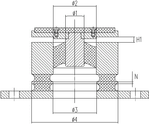
[0058] Such as image 3 As shown, on the basis of Example 1, in order to increase the stiffness of the first segment (stiffness under small displacement), the inner diameter of the metal jacket Φ2 is reduced, the outer diameter of the metal inner jacket is increased Φ1, and the inner surface of the metal jacket and the metal inner surface are reduced. The distance between the outer surfaces of the sleeve. In order to advance the inflection point of variable stiffness, the distance H1 between the metal bottom plate 7 and the metal jacket 4 is reduced. In order to increase the large displacement stiffness, the number of layers N of the metal separator 2 can be increased, and at the same time, the outer diameter Φ4 of the metal separator 2 (the metal separator is cylindrical) can be increased, and the inner diameter of the opening Φ3 can be reduced. By adjusting the parameters Φ1, Φ2, Φ3, Φ4, H1, and N, the combination of various stiffnesses and multi-position inflection points ...


PUM


Abstract

The invention discloses a manufacturing and assembling method for a variable-rigidity traction rubber pile and a rigidity varying method. The manufacturing and assembling method includes the following steps that a metal bottom board, a bottom elastic rubber body, a metal partition, a metal outer sleeve and a bottom elastic rubber body are bonded together through an adhesive in a high-temperature vulcanized manner; a metal inner sleeve is placed in the metal outer sleeve, so that the top of the metal inner sleeve extends out of the upper end face of the metal outer sleeve at the preset height, and the metal outer sleeve and the metal inner sleeve are vulcanized and bonded together through an upper elastic rubber body; a metal top board is connected with the top of the metal inner sleeve in an interference fit manner, so that an interval is reserved between the metal top board and the upper end face of the metal outer sleeve; and a wear-resisting board is installed on the metal top board through fastening screws. The manufacturing and assembling method is simple and convenient, and a product manufactured through the method can meet the requirement that the product has the trend of the linear flexible damping effect in the early stage and the variable rigidity requirement that the rigidity is acutely increased when deformation is increased in the later stage. A wear-resisting material is added to a stressed face of the product, so that wear of the product under the working condition is reduced, and the dynamic performance of a vehicle can be achieved.

Description

technical field [0001] The invention relates to the technical field of vibration reduction of locomotives and vehicles. Background technique [0002] The traction rubber pile is a commonly used rubber-metal composite damping element, which is used for the floating traction device in the center of the bogie. It is widely used in the secondary traction system of rolling stock. It is the main component of the secondary traction. The traction and braking load between the car body and the cushioning of longitudinal impact. The traction rubber stack should have the following properties: sufficient strength to ensure the effective transmission of traction and braking loads; reasonable elastic parameters to improve the comfort of vehicle operation. The most common application structure of the traction rubber stack is the composite laminated structure of metal parts and rubber. The performance of the laminated rubber stack structure can basically meet the use of certain types of wor...

Claims


Application Information

Patent Timeline
IPC IPC(8): B61F5/08
Inventor 田志刚张春良柳禄泱孙海燕
Owner ZHUZHOU TIMES NEW MATERIALS TECH
Why Eureka
Try Eureka