
Magnetic loop type infinitely variable-speed device

A continuously variable transmission device, a technology of a variable speed device, applied in the field of transmission, can solve problems such as inability to ensure accurate transmission ratio and inability of a continuously variable transmission mechanism, and achieve the effects of simple structure, low cost and long service life

Pending Publication Date: 2017-03-22
赵克中
View PDF3 Cites 2 Cited by
  • Summary
  • Abstract
  • Description
  • Claims
  • Application Information

AI Technical Summary

Problems solved by technology

[0008] The purpose of the present invention is to provide a magnetic ring type continuously variable transmission device, which solves the shortcomings of the existing continuously variable transmission mechanism that cannot continuously change the speed of the entire stroke, cannot guarantee an accurate transmission ratio, and the two transmission mechanisms have no braking function.

Method used


Image

  • Magnetic loop type infinitely variable-speed device

Examples

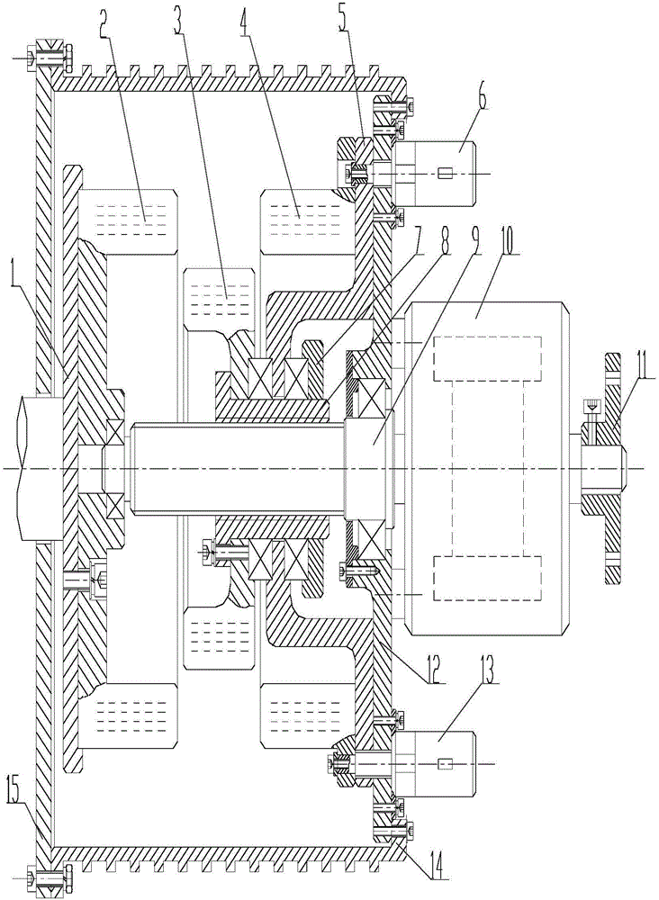

Embodiment Construction

[0024] The present invention will be described in detail below in conjunction with the accompanying drawings and specific embodiments.

[0025] The structure of a magnetic ring type continuously variable transmission device provided by the present invention is as follows: figure 1 As shown, it consists of two parts: a permanent magnet transmission device and a gear transmission device.

[0026] The composition and functions of the permanent magnet transmission system are as follows:

[0027] The permanent magnet transmission device is composed of three parts: the active permanent magnet ring rotor, the intermediate permanent magnet ring rotor and the braking permanent magnet ring stator. in:

[0028] (1) Active permanent magnet ring rotor: a cylindrical whole composed of a power input disk 1 and an active permanent magnet ring 2, and the power input disk 1 and the active permanent magnet ring 2 are mechanically connected with screws. The active permanent magnet ring 2 is an...


PUM


Abstract

Disclosed in the invention is a magnetic loop type infinitely variable-speed device comprising an active permanent magnetic ring in an active rotation manner and an intermediate permanent magnetic ring. When the intermediate permanent magnetic ring enters the active permanent magnetic ring, the intermediate permanent magnetic ring is driven to make rotation by a magnetic torque generated by cutting magnetic force lines mutually; the intermediate permanent magnetic ring drives a spline shaft to make synchronous rotation; and a driving force is inputted into a gear variable-speed unit. In addition, the magnetic loop type infinitely variable-speed device also includes a static braking permanent magnetic ring. After exit of the rotating intermediate permanent magnetic ring, the braking permanent magnetic ring sleeves the intermediate permanent magnetic ring and rotation of the intermediate permanent magnetic ring is stopped by a magnetic torque generated by cutting magnetic force lines mutually, so that the spline shaft and the gear variable-speed unit connected with the spline shaft rotates at a reduced speed or stops rotating. According to the magnetic loop type infinitely variable-speed device, infinitely variable-speed, braking, and overloaded slip frequency protection functions can be realized simultaneously; and the torque is transmitted by the magnetic field, so that the harmful vibration, wearing, and breakage can be eliminated substantially, the service life of the variable-speed device can be prolonged, and the damage caused by overloading is avoided.

Description

technical field [0001] The invention belongs to the technical field of transmissions, and in particular relates to a magnetic ring type continuously variable transmission device. Background technique [0002] The transmission device is a transmission device that makes the output shaft obtain different speeds under the condition of constant input speed. It is a component often used in the power transmission process of mechanical systems, and is widely used in petrochemical, power industry, automobile manufacturing, mining and shipping, aerospace, steel industry, papermaking and other industries. With the continuous development of science and technology, the application fields of transmissions are constantly expanding, and the technology is also constantly developing, and new products and technologies emerge in endlessly. [0003] There are many types of transmission devices, which are generally divided into stepped transmission mechanisms and continuously variable transmissi...

Claims


Application Information

Patent Timeline
Patent Type & Authority Applications(China)
IPC IPC(8): H02K49/10
CPCH02K49/102H02K49/106
Inventor 赵克中彭顺保刘嵘郝建平
Owner 赵克中
Learn More