Low-energy acoustooptic controlled LED lamp device

An LED lamp device and sound-light control technology, which is applied to lighting devices, components of lighting devices, and damage prevention measures for lighting devices, can solve problems such as troublesome production and assembly, reduced service life, and high heat generation of LED lights, and achieve The production and assembly are simple and convenient, the service life is long, and the heat dissipation effect is good.

Inactive Publication Date: 2016-05-04
SHAOXING UNIVERSITY
View PDF6 Cites 3 Cited by
  • Summary
  • Abstract
  • Description
  • Claims
  • Application Information

AI Technical Summary

Problems solved by technology

[0002] Sound and light control lights are an important part of home lighting (such as corridors, bathrooms, alleys, etc.), traditional sound and light control lights are a combination of sound and light control switches and ordinary incandescent lamps, ordinary incandescent lamps have short life and low light efficiency caused a huge waste of energy
Therefore, LED acousto-optic control lamps are now produced, which have a good energy-saving effect. However, LED lamps generate a lot of heat and need to be dissipated in time, otherwise they are easily damaged and greatly reduce the service life. However, the heat dissipation effect of existing LED acousto-optic control lamps is not good. Ideal, but troublesome to make and assemble

Method used


Image

  • Low-energy acoustooptic controlled LED lamp device
  • Low-energy acoustooptic controlled LED lamp device
  • Low-energy acoustooptic controlled LED lamp device

Examples


Embodiment Construction

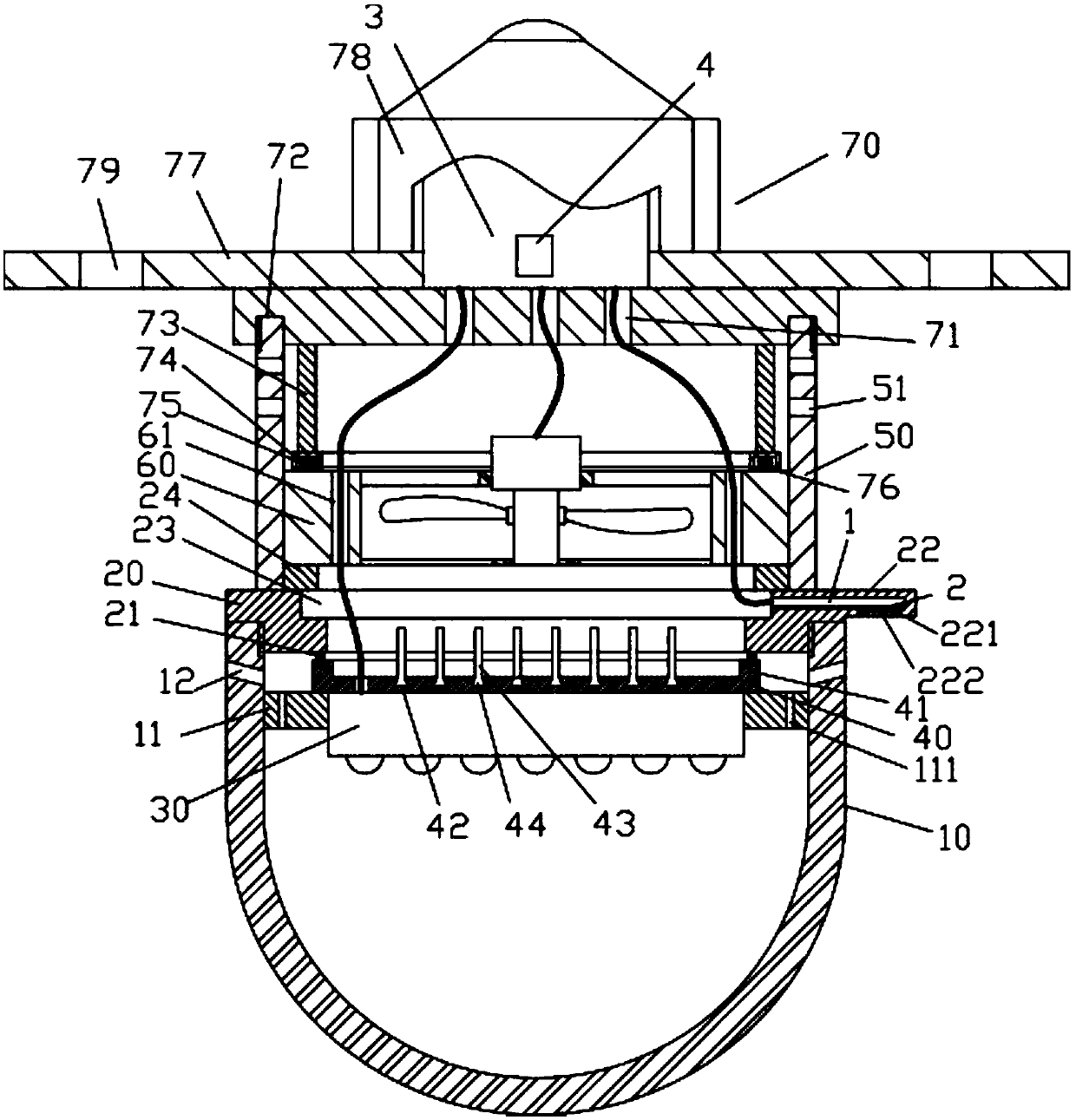
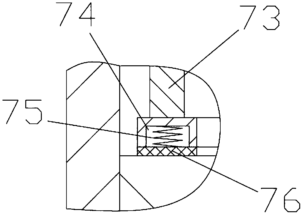
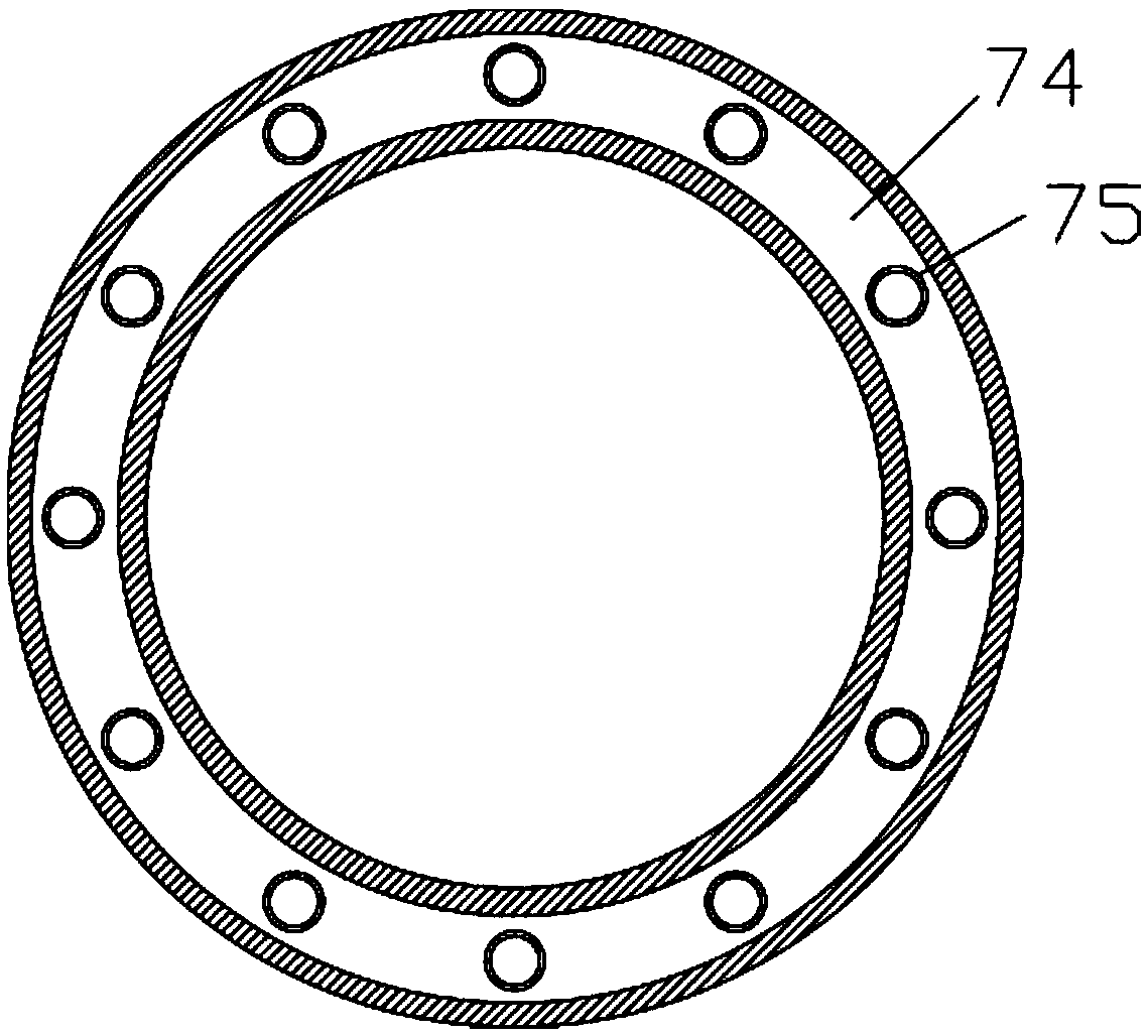
[0020] Examples, see e.g. Figure 1 to Figure 4 As shown, a low energy consumption acousto-optic control LED lamp device includes a lampshade body 10, the inner wall of the top of the lampshade body 10 has a connecting thread, the upper connecting cover 20 is screwed into the connecting thread, and the upper connecting cover 20 is pressed against the On the top surface of the lampshade body 10, an annular fixing ring 11 is fixed on the inner wall of the lampshade body 10, the LED lamp board 30 is inserted into the annular fixing ring 11, and the top surface of the LED lamp board 30 is fixed with an aluminum alloy heat sink 40, The aluminum alloy cooling plate 40 is pressed against the top surface of the annular fixed ring 11, and the bottom surface of the upper connection cover 20 is fixed with an annular elastic ring 21, and the annular elastic ring 21 is pressed against the upper top surface of the aluminum alloy cooling plate 40, and the upper connection One side of the cov...


PUM


Abstract

The invention discloses a low-energy acoustooptic controlled LED lamp device, comprising a lampshade; an inner sidewall of the top of the lampshade is provided with connecting threads; an upper connecting cover is in threaded connection with the connecting threads and pressed against a top end face of the lampshade; an annular fixing ring is fixed on an inner sidewall of the lampshade; an LED lamp panel is inserted and nested into the annular fixing ring; an aluminum alloy heating panel is fixed on a top surface of the LED lamp panel and pressed against a top surface of the annular fixing ring; an annular elastic ring is fixed on a bottom surface of the upper connecting cover and pressed against a top surface of the aluminum alloy heating panel; a connecting piece extending radially and outwardly is arranged on one side of the upper connecting cover; a connecting circuit board is fixed in a placement groove formed in the connecting piece, and a photosensitive diode is fixed on the connecting circuit board; a through hole is formed in a bottom surface, facing the connecting piece, of the photosensitive diode, and a protective transparent block is fixed on a bottom surface of the connecting piece and covers the through hole; the low-energy acoustooptic controlled LED lamp device is good in heat dissipation effect, simple and convenient to manufacture and assemble, and long in service life.

Description

Technical field: [0001] The invention relates to the technical field of energy-saving lamps, in particular to a low-energy-consumption acousto-optic control LED lamp device. Background technique: [0002] Sound and light control lights are an important part of home lighting (such as corridors, bathrooms, alleys, etc.), traditional sound and light control lights are a combination of sound and light control switches and ordinary incandescent lamps, ordinary incandescent lamps have short life and low light efficiency Caused a huge waste of energy. Therefore, LED acousto-optic control lamps are now produced, which have a good energy-saving effect. However, LED lamps generate a lot of heat and need to be dissipated in time, otherwise they are easily damaged and greatly reduce the service life. However, the heat dissipation effect of existing LED acousto-optic control lamps is not good. Ideal, but cumbersome to make and assemble. Invention content: [0003] The object of the p...

Claims


Application Information

Patent Timeline
IPC IPC(8): F21K9/20F21V17/12F21V19/00F21V29/89F21V17/16F21V23/00F21V17/10F21V29/67F21V23/04F21V29/83F21V29/506F21V29/76F21V15/04F21Y115/10
CPCF21V15/04F21V17/10F21V17/12F21V17/16F21V19/0015F21V23/00F21V23/0442
Inventor 卢丽娟张新华鲁志康何绍木尹黎明张苏敏
Owner SHAOXING UNIVERSITY
Why Eureka
Try Eureka