Semi-rigid mechanical deployment into deceleration landing gear

A landing device and semi-rigid technology, which is applied in the directions of aerospace vehicle landing device, aerospace safety/emergency device, aerospace vehicle heat protection device, etc. limited and other problems, to achieve the effect of reducing the envelope requirement, reducing the weight and complexity of the system, and improving the deceleration effect

Inactive Publication Date: 2017-08-04
BEIJING SPACE TECH RES & TEST CENT +1
View PDF4 Cites 0 Cited by
  • Summary
  • Abstract
  • Description
  • Claims
  • Application Information

AI Technical Summary

Problems solved by technology

The existing design of semi-rigid mechanical deployment and re-entry deceleration landing structure can provide a large aerodynamic deceleration surface, which can well solve the problems of large load entry, deceleration, and landing. At the same time, there are some disadvantages: first, the storage ratio limited
Therefore, from the perspective of engineering application, the expansion area of ​​the aerodynamic deceleration surface of this structure cannot be "infinitely" large, the deceleration effect is limited, and other methods such as parachutes are still needed for secondary deceleration; second, the structure does not have buffer after reverse reconstruction The landing stage mainly relies on the thrust reverser engine for buffering, and the system is heavy and complex

Method used


Image

  • Semi-rigid mechanical deployment into deceleration landing gear
  • Semi-rigid mechanical deployment into deceleration landing gear
  • Semi-rigid mechanical deployment into deceleration landing gear

Examples


Embodiment Construction

[0020] The present invention will be described in further detail below in conjunction with the accompanying drawings.

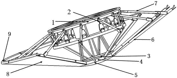
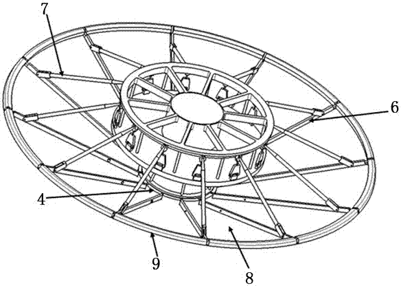
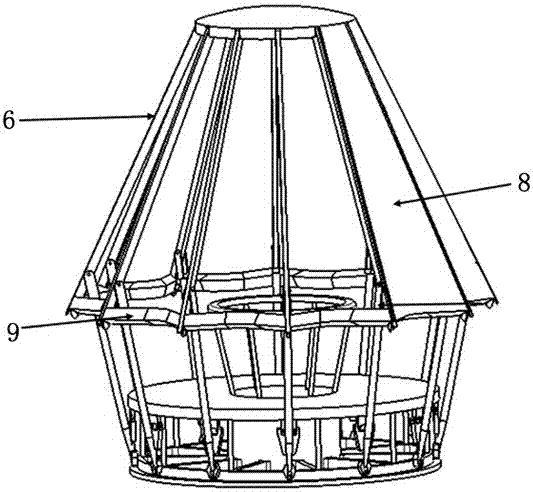
[0021] Such as Figures 1 to 5 As shown, the semi-rigid mechanical deployment reentry deceleration landing device of the present invention includes a main body 1, an elastic reverse drive rod 2, a control ring 3, a nose cone ring 4, a rigid nose cone 5, spokes 6, a connecting rod 7, a semi-rigid Heat shield 8 and flexible heat shield 9. Main body 1, control ring 3, nose cone ring 4 and rigid nose cone 5 are arranged sequentially from top to bottom. The cone ring 4 is fixed on the top of the rigid nose cone 5 by bolts, and the rigid nose cone 5 is located at the lowermost end, and its section is similar to a fan. A plurality of cables are connected between the nose cone ring 4 and the control ring 4, and the cables are wound on a motor (not shown in the figure), and the motor rotates to change the length of the cables to realize the relative movement between...


PUM


Abstract

The invention discloses a semi-rigid mechanically-unfolded deceleration entering landing device and belongs to the field of spacecraft entrance and return. The semi-rigid mechanically-unfolded entering decelerated landing device comprises a body, a control ring, a rigid head cone, a semi-rigid heat insulation cover, a semi-rigid heat insulation cover control mechanism and a flexible heat insulation cover mechanism. The body is fixedly connected with the control ring. A drive mechanism is connected between the control ring and the rigid head cone and controls the control ring and the rigid head cone to move relatively. The semi-rigid heat insulation cover control mechanism is covered with the semi-rigid heat insulation cover and hinged to the body and the rigid head cone and controls the semi-rigid heat insulation cover to be unfolded or folded. The flexible heat insulation cover mechanism capable of being unfolded outwards secondarily is arranged on the outer side of the semi-rigid heat insulation cover. The total area of the unfolded device is larger than the primarily-unfolded area, the size is kept small in a folded transmission state, the storage ratio of the device is increased, the deceleration effect of a pneumatic face is improved, the system complexity is lowered, and two-stage deceleration and landing buffering are organically unified.

Description

technical field [0001] The invention relates to a deceleration landing device, in particular to a semi-rigid mechanical deployment and entry deceleration landing device, which belongs to the technical field of spacecraft entry and return. Background technique [0002] With the continuous deepening of deep space exploration, effective deceleration is required when large payloads enter stars with atmospheric environments. The existing design of semi-rigid mechanical deployment and re-entry deceleration landing structure can provide a large aerodynamic deceleration surface, which can well solve the problems of large load entry, deceleration, and landing. At the same time, there are some disadvantages: first, the storage ratio limited. The larger the area of ​​the expanded aerodynamic deceleration surface, the larger the volume of the retracted state, and the higher the demand for the envelope of the rocket fairing. Therefore, from the perspective of engineering application, t...

Claims


Application Information

Patent Timeline
Patent Type & Authority Patents(China)
IPC IPC(8): B64G1/62B64G1/58
CPCB64G1/58B64G1/62
Inventor 张鹏李旭东尚明友侯向阳童明波张红英
Owner BEIJING SPACE TECH RES & TEST CENT
Why Eureka
Try Eureka