Cloth conveying device for textiles

A cloth conveying and chainring technology, which is applied in the direction of conveyors, conveyor objects, transportation and packaging, etc., can solve the problems of worker safety risks, low work efficiency, long time consumption, and high labor intensity of workers, so as to increase efficiency and reduce Labor intensity, the effect of improving work efficiency

Inactive Publication Date: 2016-05-18
吴江市盛泽信达绸厂
View PDF6 Cites 9 Cited by
  • Summary
  • Abstract
  • Description
  • Claims
  • Application Information

AI Technical Summary

Problems solved by technology

[0002] At present, textile enterprises generally use carts for short-distance transportation after the rolls of fabric are produced. This transportation method takes a long time and the labor intensity of the workers is high.
[0003] It is particularly obvious that when the rolls of fabrics are packed in boxes or stored at close range, workers need to manually lift the fabrics due to the different stacking heights of the fabrics, which causes problems such as safety risks and low work efficiency for workers.

Method used


Image

  • Cloth conveying device for textiles
  • Cloth conveying device for textiles

Examples


Embodiment Construction

[0019] Embodiment of the present invention is described below in conjunction with accompanying drawing, embodiment does not constitute limitation of the present invention;

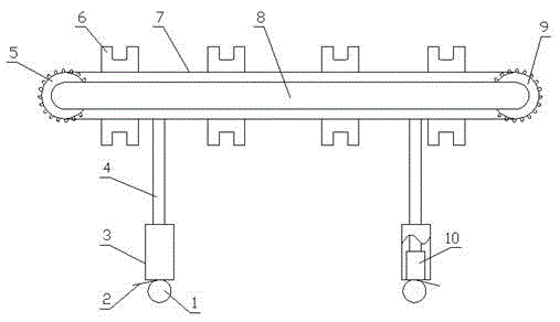
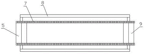
[0020] Such as figure 1 , figure 2 As shown, the cloth conveying device for weaving has a structure comprising a frame 8; the two ends of the frame 8 are respectively fixed with a driven tooth plate 5 and a driving tooth plate 9, and during use, the driven tooth plate 5 acts to The power chain 7 turns, and the driving chain 9 plays the role of providing power to the power chain 7. The driving chain 9 is driven by internal electric power; the outer surface of the driven chain 5 and the driving chain 9 are engaged with a ring Power chain 7, when in use, ring-shaped power chain 7 engages with the teeth of the tooth plate, drives power chain 7 to move by the rotation of active tooth plate 9.

[0021] In the above embodiment, specifically, the upper surface of the dynamic chain 7 is provided with a number of...


PUM


Abstract

The invention relates to the field of textiles, in particular to a cloth conveying device for textiles. The cloth conveying device has a continuous conveying function, can improve the conveying efficiency and reduce the transporting safety risk of workers, and is suitable for various conveying heights. The cloth conveying device is characterized by comprising a rack, wherein a driven chain wheel and a driving chain wheel are respectively fixed at the two ends of the rack; a ring-shaped dynamic chain is meshed between the driven chain wheel and the driving chain wheel; a plurality of positioning teeth are arranged on the upper surface of the dynamic chain; the rack is propped against the ground through an upper bracket and a lower bracket fixed on the lower surface of the rack; a hydraulic cylinder is arranged inside the lower bracket; and the top end of the hydraulic cylinder is in contact with the bottom end of the upper bracket. The cloth conveying device is stable to work, convenient to maintain, long in service life and applicable to conveying of textile fabric rolls.

Description

technical field [0001] The invention relates to the field of textiles, in particular to a cloth conveying device for textiles. Background technique [0002] At present, textile enterprises generally use carts for short-distance transportation after the rolls of fabric are produced. This transportation method takes a long time and the labor intensity of workers is high. [0003] It is particularly obvious that when the rolls of fabric are packed or stored in close proximity, workers need to manually lift the fabric due to the different stacking heights of the fabric, which causes problems such as safety risks and low work efficiency for workers. Contents of the invention [0004] The technical task of the present invention is to provide a textile cloth conveying device for the above-mentioned deficiencies in the prior art. The textile cloth conveying device is continuous conveying, which can improve the conveying efficiency, reduce the safety risk of workers' handling, and ...

Claims


Application Information

Patent Timeline
Patent Type & Authority Applications(China)
IPC IPC(8): B65G17/42B65G41/00
CPCB65G17/42B65G41/001B65G41/008
Inventor 周根林
Owner 吴江市盛泽信达绸厂
Why Eureka
Try Eureka