
Frame fixing base machining device and fence machining production line

A technology of processing device and fixed seat, applied in metal processing equipment, manufacturing tools, other manufacturing equipment/tools, etc., can solve the problems of troublesome assembly and disassembly, inconvenient transportation, poor stability, etc., to achieve high production efficiency and enhance urban culture The effect of quality and service life improvement

Active Publication Date: 2020-06-30
湖南翰坤实业有限公司
View PDF9 Cites 4 Cited by
  • Summary
  • Abstract
  • Description
  • Claims
  • Application Information

AI Technical Summary

Problems solved by technology

However, the existing fence structure is poor in stability, cumbersome to assemble and disassemble, and inconvenient to transport

Method used


Image

  • Frame fixing base machining device and fence machining production line
  • Frame fixing base machining device and fence machining production line
  • Frame fixing base machining device and fence machining production line

Examples


Embodiment 1

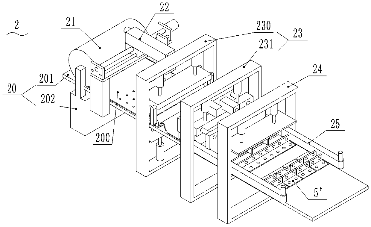
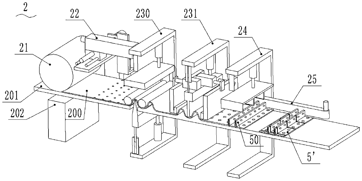
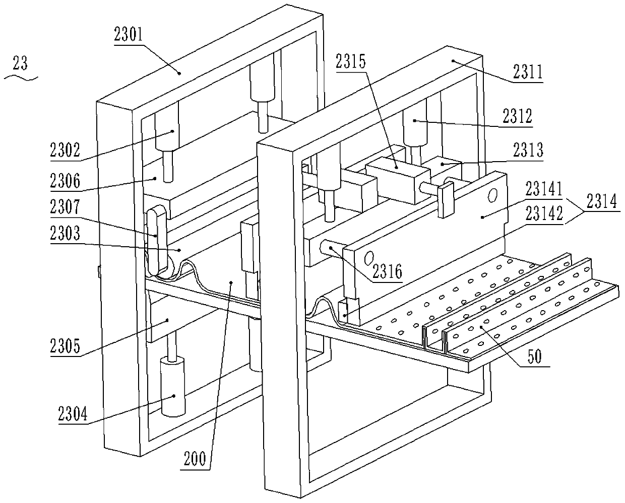
[0067] Such as Figure 1-7 As shown in , 28, the processing device 2 for the frame fixing seat provided in this embodiment, the frame fixing seat 5' includes a fixing plate 51', and two splints 50' arranged in parallel and alternately in the middle of the fixing plate 51' , the splint 50' is provided with a first through hole 501', and both edges of the fixing plate 51' are provided with a second through hole 510'; the frame holder processing device 2 includes a second working platform 20, The second reel mechanism 21 for winding the second iron plate 200, the second extruding mechanism 23 for extruding the two straight plates 50 parallel to each other on the second iron plate 200, for the second iron plate 200 The third cutting mechanism 24 for cutting the board 200 and two straight boards 50, the width of the straight board 50 is equal to the width of the splint 50', and the length of the straight board 50 is N times the length of the splint 50', N ≥1, N is a natural number...

Embodiment 2

[0094] Such as Figure 1-30As shown, a fence production and processing system provided in this embodiment, the fence 100' includes a mesh plate 1', a frame 2', a frame fixing seat 5', a support rod 3' and a support rod fixing seat 6' , the frame 2' includes an outer frame 20' and a plurality of inner reinforcing tubes 21'; the enclosure production and processing system includes:

[0095] A blanking machine for blanking the mesh plate 1', the support rod 3' and the inner reinforcing tube 21';

[0096] An outer frame processing device 3 for processing the outer frame 20';

[0097] The frame fixing seat processing device 2 described in Embodiment 1 for processing the frame fixing seat 5';

[0098] A support rod holder processing device 1 for processing the support rod holder 6';

[0099] A butt welder for welding the outer frame 20' and the inner reinforcing tube 21', as well as the welding of the mesh plate 1' and the frame 2';

[0100] A paint spraying machine for spraying ...


PUM


Abstract

The invention discloses a frame fixing base machining device. The frame fixing base machining device comprises a second working platform, a second winding drum mechanism used for winding a second ironplate, a second extrusion forming mechanism used for extruding two parallel straight plates on the second iron plate, and a third cutting mechanism used for cutting the second iron plate and the twostraight plates, wherein the second winding drum mechanism, the second extrusion forming mechanism and the third cutting mechanism are sequentially arranged on the second working platform; and the frame fixing base machining device further comprises a second conveying mechanism arranged on the second working platform and used for conveying the second iron plate. According to the frame fixing basemachining device, automatic machining of a frame fixing base is achieved, the production efficiency is high, the device can be suitable for batch production, and manpower is saved. The invention further discloses a fence machining production line. The production efficiency of a fence is greatly improved, the fence machining production line is suitable for batch production, the manpower is saved, and the production cost is saved.

Description

technical field [0001] The invention relates to the technical field of fence production equipment, in particular to a frame fixing seat processing device and fence processing production line. Background technique [0002] Fences are mainly suitable for construction sites and urban road construction, used to protect and divide construction areas, isolate the external environment, and protect and shield. However, the existing fence structure has poor stability, troublesome assembly and disassembly, and inconvenient transportation. In order to improve the performance of the fence, our company has developed a new fence 100', such as Figure 24-30 As shown, it includes a mesh plate 1', a frame 2', a frame fixing seat 5', a support rod 3' and a support rod fixing seat 6', and the frame 2' includes an outer frame 20' and a plurality of inner reinforcing tubes 21' , wherein the inner reinforcing tube 21' includes a plurality of transverse reinforcing tubes 211' and longitudinal rei...

Claims


Application Information

Patent Timeline
Patent Type & Authority Applications(China)
IPC IPC(8): B21C23/21B21C33/00B23K26/38B23D79/00B23P23/00
CPCB21C23/211B21C23/212B21C33/00B23D79/00B23K26/38B23P23/00
Inventor 康望才
Owner 湖南翰坤实业有限公司
Learn More