
Reverse blowing system of road sweeper and road sweeper

A technology of back blowing and road sweeper, applied in the field of sanitation machinery, can solve the problems of insufficient back blowing, noise, inconvenience for operators, etc., and achieve the effect of reducing secondary dust.

Inactive Publication Date: 2016-05-18
XCMG CONSTR MACHINERY
View PDF8 Cites 6 Cited by
  • Summary
  • Abstract
  • Description
  • Claims
  • Application Information

AI Technical Summary

Problems solved by technology

[0005] 1. The dust brought into the cleaning centrifugal fan by the air flow will also be directly discharged to the atmosphere, causing secondary dust;
[0006] 2. If several reverse blowing pipes are drawn from the outlet of the centrifugal fan for cleaning and introduced into the suction cup at the same time, the amount of reverse blowing may be insufficient;
[0007] 3. The aerodynamic noise source generated inside the centrifugal fan for cleaning will directly spread to the outside through the blowback pipe, causing noise problems;
[0008] 4. To control the start and stop of reverse blowing and the air volume, the valve plate located at the outlet of the centrifugal fan for cleaning must be adjusted, which is inconvenient for the operator to perform this operation in the cab

Method used


Image

  • Reverse blowing system of road sweeper and road sweeper
  • Reverse blowing system of road sweeper and road sweeper

Examples


no. 1 example

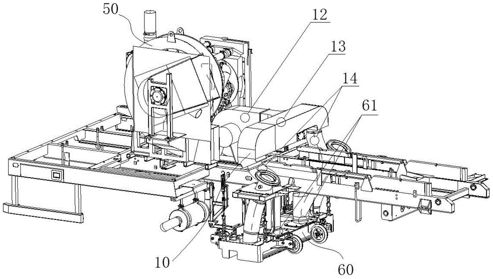
[0035] figure 1 It is a structural schematic diagram of the blowback system of the road sweeper according to the first embodiment of the present invention.

[0036] like figure 1 As shown, the blowback system 10 of the road sweeper of the first embodiment includes a blowback fan and a flow path for blowback.

[0037] The inlet of the reverse blowing fan is connected with the atmosphere, and the outlet of the reverse blowing blower is connected with the inlet of the reverse blowing flow path. In the first embodiment, the reverse blowing fan is a reverse blowing centrifugal fan 12, and the reverse blowing centrifugal fan 12 and the cleaning centrifugal fan 50 are independent of each other. The reverse blowing centrifugal fan 12 and the cleaning centrifugal fan 50 are all arranged on the chassis of the road sweeper. The reverse blowing centrifugal fan 12 is installed in the middle part of the chassis of the road sweeper.

[0038] The reverse blowing centrifugal blower 12 purp...

no. 2 example

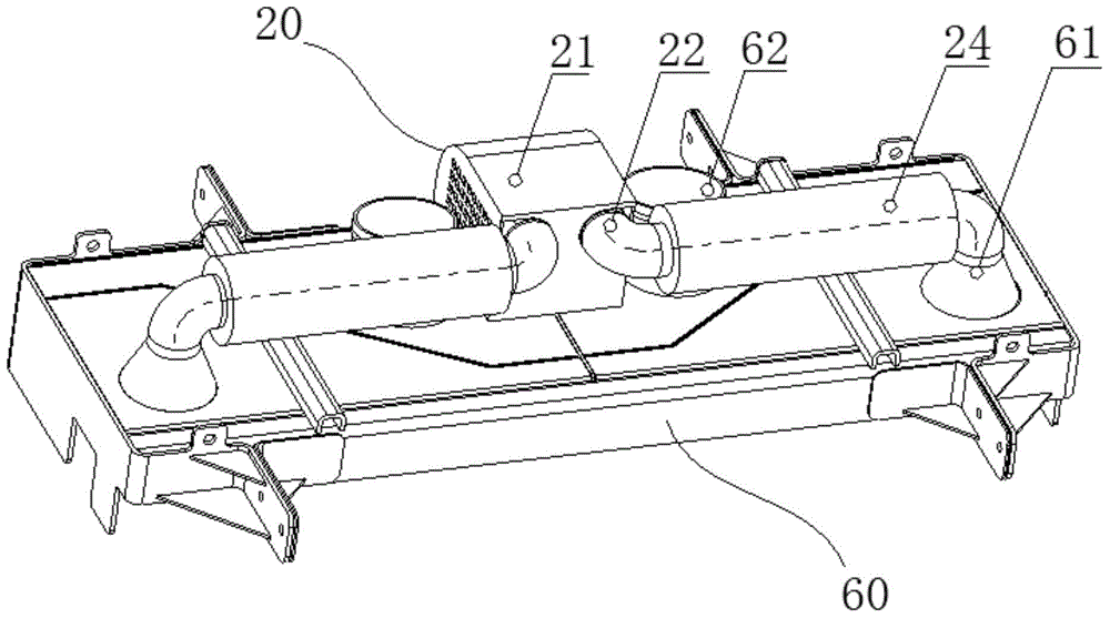
[0046] figure 2 It is a structural schematic diagram of the blowback system of the road sweeper according to the second embodiment of the present invention.

[0047] like figure 2 As shown, the blowback system 20 of the road sweeper of the second embodiment includes a blowback blower, a blowback flow path and a noise reduction protective cover 21 .

[0048] In the second embodiment, the reverse blowing fan is a reverse blowing centrifugal fan, and the reverse blowing centrifugal fan and the cleaning centrifugal fan are independent of each other. The reverse blowing centrifugal fan is arranged in the middle of the top surface of the suction cup 60 and between the two suction ports 62 of the suction cup 60 for connecting to the dustbin. Dust and sundries are sucked into the dustbin from two suction ports 62 of the suction cup 60. Noise elimination protective cover 21 covers are located at the outside of reverse blowing centrifugal fan, therefore in figure 2 The reverse bl...


PUM


Abstract

The invention discloses a reverse blowing system of a road sweeper and the road sweeper. The reverse blowing system comprises a reverse blowing fan and a reverse blowing flow path, wherein an inlet of the reverse blowing fan communicates with atmosphere, and an outlet of the reverse blowing fan communicates with an inlet of the reverse blowing flow path; an outlet of the reverse blowing flow path communicates with reverse blowing interfaces, wherein the reverse blowing interfaces are arranged on a sucker of the road sweeper and communicate with an inner cavity of the sucker. Because the reverse blowing system adopts the reverse blowing fan which is independent of a centrifugal fan for sweeping, outside clean air is used for reverse blowing, and reversed blown air carrying dust from a dustbin cannot be directly exhausted to the atmosphere; therefore, secondary raising dust is reduced.

Description

technical field [0001] The invention relates to the field of sanitation machinery, in particular to a blowback system of a road sweeper and the road sweeper. Background technique [0002] In the field of sanitation machinery, the main working parts of road sweepers are centrifugal fans for cleaning, brushes and suction cups. The main working process of the road sweeper is as follows: During the driving and working process of the road sweeper, under the action of the sweeping brush, the dust and debris on the road surface are gathered near the suction cup, and at the same time, the centrifugal fan for cleaning is running at high speed, and in the dustbin High negative pressure is generated, and under the action of high negative pressure, dust and debris are sucked into the dustbin through the suction port of the suction cup. In order to improve the cleaning efficiency of the road sweeper and make the road surface be picked up more cleanly, single or multiple anti-air blowing...

Claims


Application Information

Patent Timeline
IPC IPC(8): E01H1/08
Inventor 庄超倪翔宇孟东阁
Owner XCMG CONSTR MACHINERY
Learn More