Dust discharging and collecting integrated device

A dust and driving device technology, which is applied in the direction of dust removal, loading/unloading, transportation and packaging, etc., can solve the problems of secondary dust overflow, increase the specific gravity of materials, and high energy consumption in operation, so as to reduce secondary dust and reduce secondary dust. Less dust, no pollution to the environment

Inactive Publication Date: 2019-04-02
PANGZHIHUA PANGANG GROUP DESIGN & RES INST
View PDF9 Cites 3 Cited by
  • Summary
  • Abstract
  • Description
  • Claims
  • Application Information

AI Technical Summary

Problems solved by technology

The first one is: ash storage bin → ash unloading valve → slide pipe, vacuum hood → ash truck. The dust generated during the ash unloading process usually consumes an air volume of 20,000m in the dust removal system 3 About / h, or even larger; the secondary dust is large and the dust capture ability is poor. Due to the gap between the dust collection hood and the carriage of the ash truck, when the material falls to the carriage, a large amount of secondary dust will overflow. Under windy conditions , the effect is worse
The second type is: ash storage bin → ash unloading valve → dust humidifier → chute → ash truck. The disadvantages are: high energy consumption for equipment operation, the power of the drive motor of the dust humidifier is ~15kw, and the water consumption is about 15t / h; The energy consumption of automobile transportation, after the material is humidified, the specific gravity of the material is increased; it is not suitable for dusty materials and hydrophobic materials that do not need to be humidified in the next process

Method used


Image

  • Dust discharging and collecting integrated device
  • Dust discharging and collecting integrated device
  • Dust discharging and collecting integrated device

Examples


Embodiment

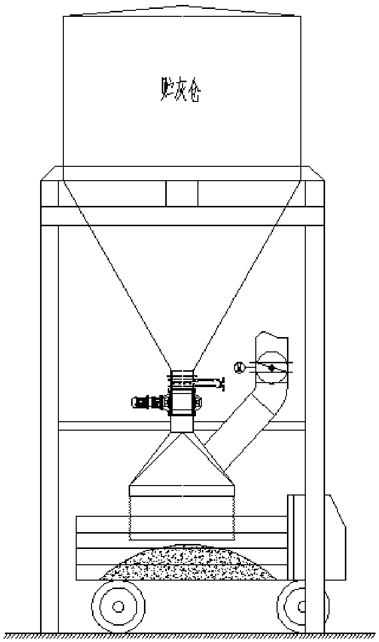
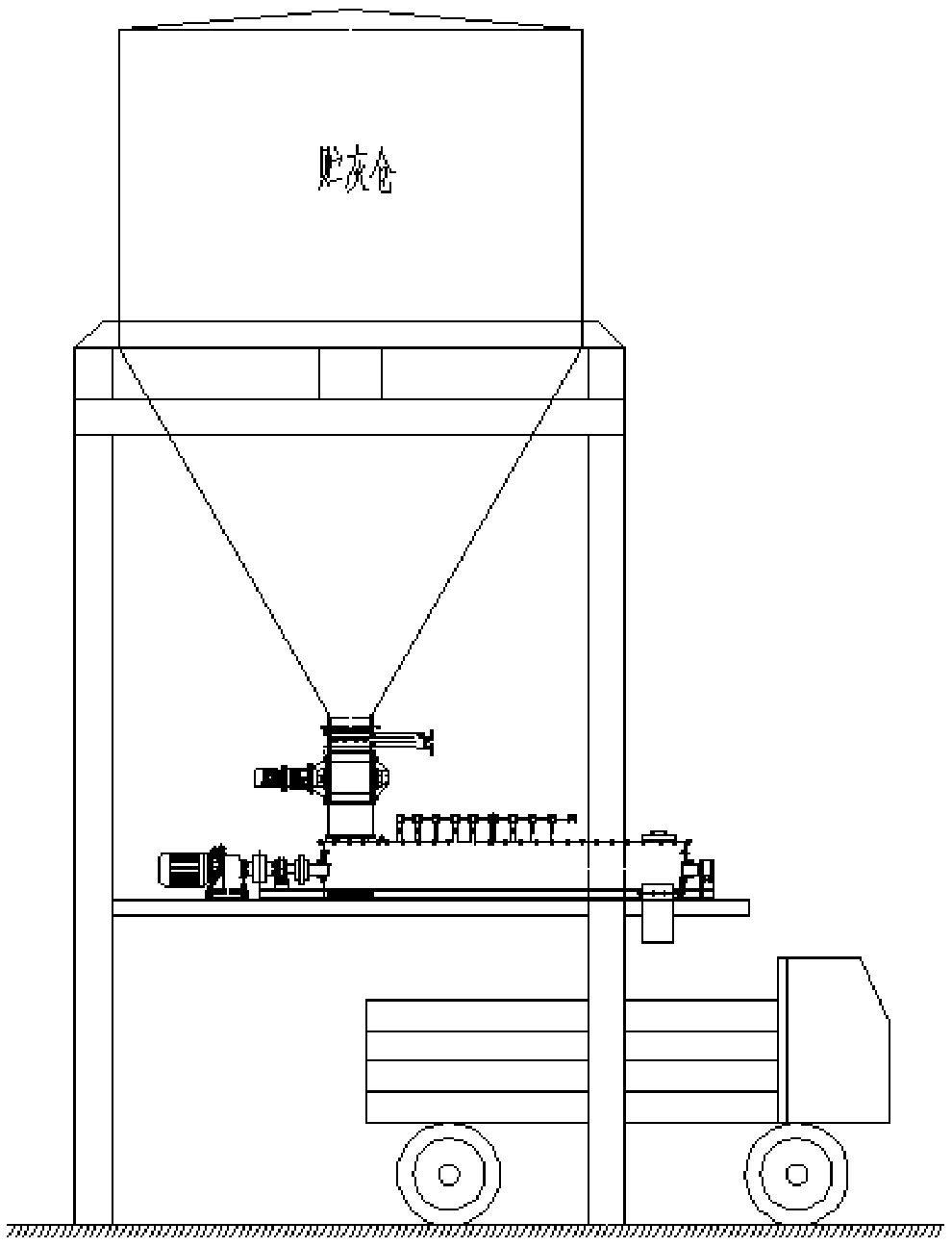
[0034] According to incomplete statistics, only the first type ( figure 1 ) And the second ( figure 2 ) The number of ash storage bins for ash unloading is more than 50. If this technical improvement can be widely used, it will not only have greater economic benefits, but also greater social benefits.

[0035] 1. Direct economic benefits:

[0036] Based on the improvement of the ash unloading process of the ash storage silo #1, 2, 3, and 4 in the vanadium extraction process optimization project of a plant in Panzhihua Iron and Steel, the cost of each technical improvement is 174,300,000 yuan, and the product profit is 15% calculated: 50×17.433×15 % = 1.30.75 million yuan;

[0037] 2. Indirect economic benefits: (Estimating that the ash storage silo discharges ash 300 times a year, and each time the ash discharge is 0.5 hours, then the annual ash discharge time is 150 hours)

[0038] Compared with the first ash unloading process (calculated based on only one ash storage bin operating ...


PUM


Abstract

The invention discloses a dust discharging and collecting integrated device in the field of dust removing equipment. The dust discharging and collecting integrated device comprises a telescopic innersleeve, a telescopic outer sleeve and a dust hood, an unloading inlet is formed in the upper end of the telescopic inner sleeve, the lower end of the telescopic inner sleeve is connected with the dusthood, the telescopic outer sleeve is arranged outside the telescopic inner sleeve in a covering mode, the upper end of the telescopic outer sleeve is connected with the telescopic inner sleeve in a sealed mode, and the lower end of the telescopic outer sleeve is communicated with the dust hood, a vent pipe is arranged at the upper end of the telescopic outer sleeve pipe and is connected to a dustremoval pipe network or is pressed and returned by a dust removal fan to return to a dust bin. The dust discharging and collecting integrated device has the advantages that the telescopic inner sleeve and the telescopic outer sleeve are arranged, the distance between the dust hood and the carriage can be adjusted during unloading, secondary flying dust can be reduced, the dust catching channel isformed through the telescopic outer sleeve, so that secondary flying dust is further reduced, the storage bin is small in energy consumption, no dust is generated, the influence of wind force is avoided, the environment pollution of the ash discharging post is avoided.

Description

Technical field [0001] The invention relates to the field of dust removal equipment, in particular to an integrated device for dust unloading and collecting. Background technique [0002] The ash storage bin is usually used in the dust removal system to store the dust collected by the dust collector. In addition to pneumatic conveying and belt conveying, the ash unloading process usually adopts the following two forms. The first one is: ash storage → ash discharge valve → slide pipe, dust hood → ash truck. The disadvantage is that the system energy consumption is high, and the dust hood needs to be designed to connect the air duct and the dust removal pipe for capturing The dust generated during the ash unloading process usually consumes 20000m of air in the dust removal system 3 / h, or even greater; the secondary dust is large and the dust capturing ability is poor. Due to the gap between the dust hood and the ash truck compartment, when the material falls into the compartment,...

Claims


Application Information

Patent Timeline
Patent Type & Authority Applications(China)
IPC IPC(8): B65G67/06B65G69/18B08B15/00
CPCB08B15/00B65G67/06B65G69/186
Inventor 刘圣李祖强胡稳华张奎胡国生
Owner PANGZHIHUA PANGANG GROUP DESIGN & RES INST
Why Eureka
Try Eureka