Laser projection light source control method and laser projection light source control device

A technology of laser projection and light source control, applied in projection devices, optics, instruments, etc., can solve problems such as threats to personal safety, damage to optical devices, and changes in the proportion of fluorescent components, and achieve the effect of ensuring quality

Active Publication Date: 2016-05-18
HISENSE VISUAL TECH CO LTD
View PDF6 Cites 9 Cited by
  • Summary
  • Abstract
  • Description
  • Claims
  • Application Information

AI Technical Summary

Problems solved by technology

[0005] In the above light source structure, if the fluorescent wheel fails or is damaged, or the color filter wheel fails or is damaged, or the laser is abnormal, it may not be possible to sequentially output the three primary colors, for example, it may cause the continuous output of the blue high-energy laser, which may cause Damage to other optical devices may even threaten personal safety, or the conversion efficiency of the fluorescent wheel decreases, resulting in changes in the proportion of fluorescent components, and eventually the projected image cannot be displayed normally, resulting in deterioration of display quality
[0006] In the prior art, an additional optical separation mechanism is installed in the normal optical path of the light source, and multiple sensors are installed, such as in the laser transmission optical path, the fluorescent wheel conversion optical path or the color filter wheel output optical path, to detect the light output of multiple positions , but on the one hand, there are differences in the types of beams at multiple positions, which may be pure color light or mixed color light, and the judgment situation is complicated. change

Method used


Image

  • Laser projection light source control method and laser projection light source control device
  • Laser projection light source control method and laser projection light source control device
  • Laser projection light source control method and laser projection light source control device

Examples


Embodiment 1

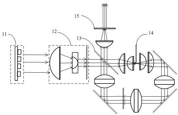
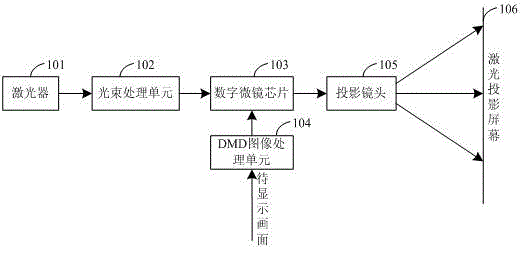
[0033] figure 2 For the structural schematic diagram of the laser projection system provided by the present invention, please refer to figure 2 , the laser projection system includes a laser 101, a beam processing unit 102, a digital micromirror chip 103, a DMD image processing unit 104, a projection lens 105, and a laser projection screen 106, and the beam processing unit 102 processes the laser beam generated by the laser 101 to obtain a light source Beam, for example, the beam processing unit 102 performs beam shaping on the laser beam generated by the laser 101, mixes the laser beam and the fluorescent beam to obtain a light source beam, and the light source beam is irradiated to the digital micromirror chip 103 (DMD), and the DMD103 The processing unit processes the processing results of the image to be displayed (such as the eigenvalues ​​of each pixel in the image to be displayed), and controls each mirror inside the DMD103 so that each mirror rotates at a different a...

Embodiment 2

[0080] Figure 7 The schematic structural diagram of the laser projection display device provided in Embodiment 2 of the present invention, which is applied to laser projection, please refer to Figure 7 , the device can include:

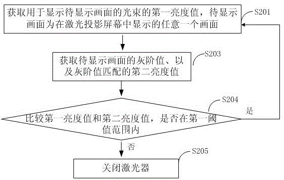
[0081] The first acquiring module 701 is configured to acquire the first brightness value of the light beam used to display the picture to be displayed, where the picture to be displayed is any picture displayed on the laser projection screen;

[0082] The second acquiring module 704, acquires the gray scale value of the picture to be displayed and the second brightness value matched with the gray scale value;

[0083]A judging module 702, configured to compare and judge whether the first brightness value and the second brightness value are within the first threshold range;

[0084] A shutdown module 703, configured to shut down the laser when the judging module judges that the first brightness value and the second brightness value are not within ...


PUM


Abstract

The invention provides a laser projection light source control method and a laser projection light source control device. The laser projection light source control method is characterized in that a first luminance value of a light beam of a frame to be displayed can be acquired, and the frame to be displayed can be any frame displayed on a laser projection screen, and then the gray-scale value of the frame to be displayed and the second luminance value matched with the gray-scale value can be acquired; by comparing the first luminance value with the second luminance value, when the comparison result is not in a first threshold value range, the laser can be switched off, and then the light source abnormity can be found out timely, and therefore the projection display frame quality can be guaranteed.

Description

technical field [0001] Embodiments of the present invention relate to the technical field of laser projection display, and in particular, to a method and device for controlling a laser projection light source. Background technique [0002] With the continuous improvement of science and technology, laser projection technology has been widely used. In laser projection technology, the image to be played is displayed on the laser projection screen through signal modulation on the beam of the laser projection light source. [0003] However, due to the high coherence and high brightness characteristics of laser, on the one hand, it will cause serious speckle phenomenon on the display screen when used as a light source. At the same time, due to the high energy density and strong penetrating power of laser, its damage is also greater . [0004] Such as figure 1 The laser projection light source shown includes a laser 11. The laser 11 can be a monochromatic laser, such as a blue la...

Claims


Application Information

Patent Timeline
Patent Type & Authority Applications(China)
IPC IPC(8): G03B21/20
CPCG03B21/2033G03B21/2053
Inventor 黄顺明曹建伟刘卫东
Owner HISENSE VISUAL TECH CO LTD
Why Eureka
Try Eureka