
UUV dynamic obstacle avoidance method based on speed obstruction method

A speed obstacle and dynamic obstacle avoidance technology, which is applied in non-electric variable control, height or depth control, vehicle position/route/height control, etc., can solve the problems of poor accuracy of moving obstacles, reduce the impact of collisions, and improve avoidance. The effect of touching safety and avoiding conservative problems

Active Publication Date: 2016-05-18
HARBIN ENG UNIV
View PDF6 Cites 30 Cited by
  • Summary
  • Abstract
  • Description
  • Claims
  • Application Information

AI Technical Summary

Problems solved by technology

[0004] The present invention solves the problem of poor accuracy of avoiding moving obstacles in the existing UUV path planning method in a dynamic environment

Method used


Image

  • UUV dynamic obstacle avoidance method based on speed obstruction method
  • UUV dynamic obstacle avoidance method based on speed obstruction method
  • UUV dynamic obstacle avoidance method based on speed obstruction method

Examples


specific Embodiment approach 1

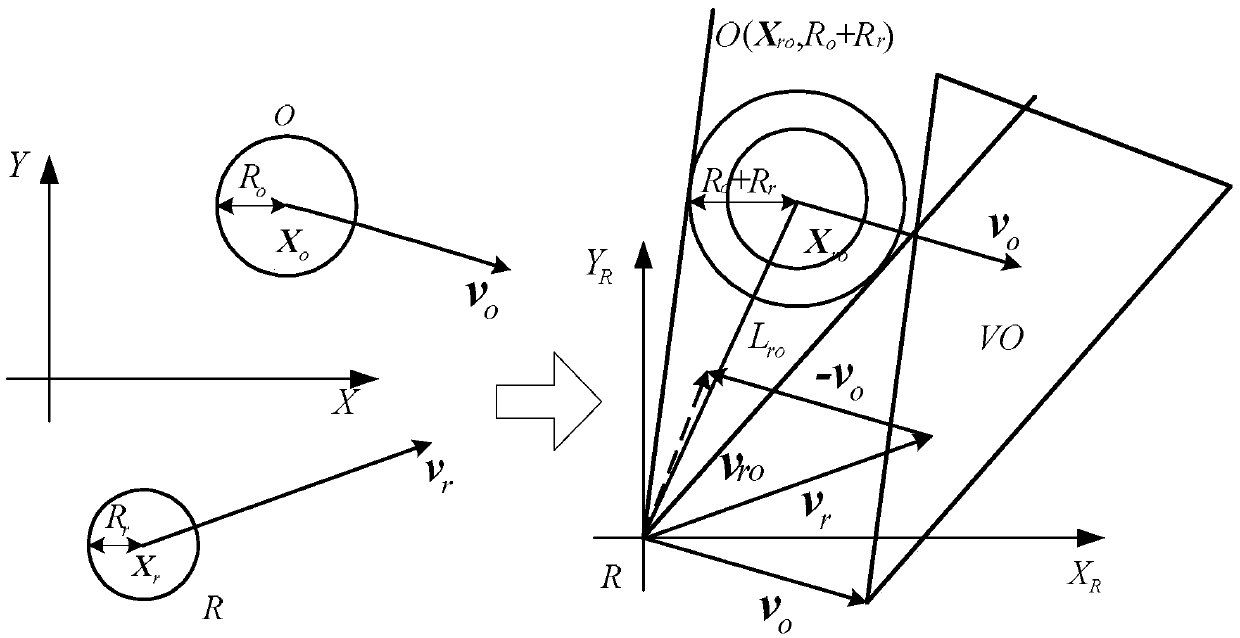
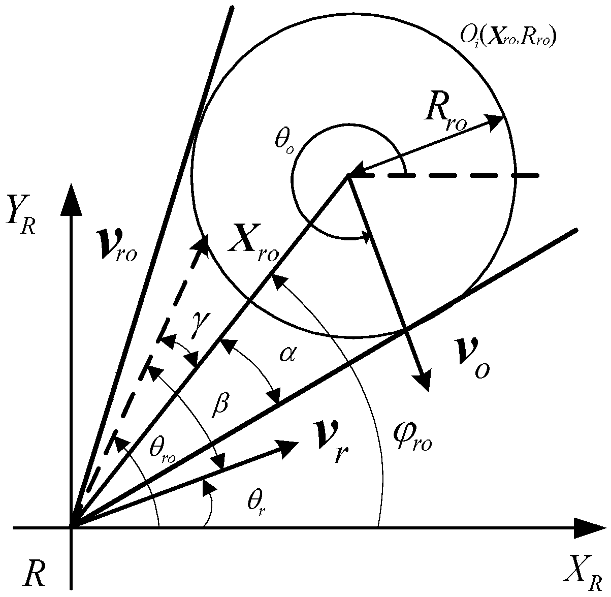
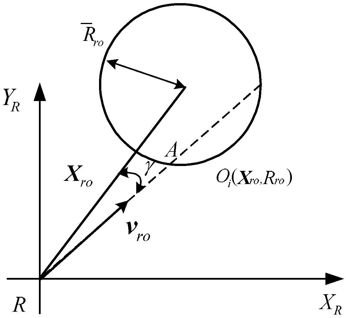
[0022] Specific implementation mode 1. Combination figure 1 , figure 2 and image 3 Describe this embodiment, a UUV dynamic obstacle avoidance method based on the speed obstacle method described in this embodiment, the specific steps of this method are:

[0023] Step 1: Transform the movement uncertainty of the obstacle into the position uncertainty, and obtain the obstacle O i lower bound estimate of radius R ro and obstacle O i upper bound estimate of the radius

[0024] Obtain the obstacle O according to the movement uncertainty of the obstacle i lower bound estimate of radius R ro : R ro =R o +R r +δ p

[0025] Obstacle O i upper bound estimate of the radius

[0026] δ p is the estimated deviation of the obstacle radius, ΔR o is the estimated upper limit of the obstacle motion uncertainty, R safe is the safety distance, R o is the obstacle radius, R r is the UUV radius;

[0027] Estimated lower bound based on obstacle radius R ro , calculate th...

specific Embodiment

[0059] The UUV sails from the starting point (0, 0) to the ending point (450, 450), the starting heading is 45°, and three obstacles O are designed to cross and meet the UUV. 1 ,O 2 ,O 3 , assuming that the moving obstacle is set as a rectangle. Forward-looking sonar is used as the collision avoidance sensing device when the position and motion information of obstacles is unknown. Use the formula (1) to get the speed risk of the moving obstacle, use the formula (3) to get the accessible speed space of the moving obstacle, use the formula (13) to get the coefficient in the optimization objective function. Then, the speed obstacle method is used to find the minimum point of the objective function value, which is used as the next waypoint to realize UUV route planning step by step. Simulation trajectory such as Figure 4 shown.


PUM


Abstract

The invention provides a UUV dynamic obstacle avoidance method based on a speed obstruction method and relates to a UUV dynamic obstacle avoidance method which solves the problem that an existing UUV route planning method is poor in accuracy when avoiding moving obstacles. According to the method, movement uncertainty of obstacles is converted into position uncertainty; according to movement uncertainty of the obstacles, the minimum safety angle alpha 1 and the maximum safety angle alpha 2 are obtained; the comprehensive speed danger degree, caused by the obstacles, of a UUV is obtained, , speed space of UUV movement is determined according to UUV dynamics constraint rule, and according to position uncertainty of the obstacles and the largest action range of the obstacles, the minimum collision time of the UUV and all the obstacles is obtained; by means of the comprehensive speed danger degree of the UUV and the minimum collision time between the UUV and all the obstacles, an optimized target route function of the UUV is obtained; by means of the speed obstruction method, the minimum value point of the target function is found to serve as the next way point of UUV movement, and a UUV movement path is planned. The UUV dynamic obstacle avoidance method is suitable for UUV dynamic obstacle avoidance.

Description

technical field [0001] The invention relates to a UUV dynamic obstacle avoidance method. Background technique [0002] With the continuous increase of human demand for marine resources, the space for human activities has gradually expanded from near-shore and shallow seas to deeper seas. UUV technology has received more and more attention, especially in the military fields of various countries. important role. [0003] The route planning of UUV (Unmanned Underwater Vehicle) is an important guarantee for the efficient and safe completion of operational tasks. However, UUV may encounter dynamic obstacles during navigation, which requires UUV to respond quickly and effectively to moving obstacles. Many scholars at home and abroad have conducted in-depth research on the problem of dynamic obstacle avoidance, and proposed many effective planning methods, such as artificial potential field method (APF), vector field histogram method, dynamic window method (DWA) and behavior meth...

Claims


Application Information

Patent Timeline
IPC IPC(8): G05D1/06
CPCG05D1/0692
Inventor 张伟王秀芳严浙平陈涛李娟滕延斌
Owner HARBIN ENG UNIV
Learn More