Permanent magnet rotating speed difference clutch and self-adaption nonsingular terminal slip form rotating speed control method thereof

A non-singular terminal and clutch technology is applied in the field of permanent magnet slip clutch adaptive non-singular terminal sliding mode speed control, which can solve problems such as external interference and parameter perturbation.

CN105591524AInactive Publication Date: 2016-05-18JIANGSU UNIV
7 Cites 7 Cited by

Patent Information

Authority / Receiving Office
CN · China
Current Assignee / Owner
Publication Date
2016-05-18
Estimated Expiration
Not applicable · inactive patent

Smart Images

  • Figure 1
    Figure 1
  • Figure 2
    Figure 2
  • Figure 3
    Figure 3
Patent Text Reader

Abstract

The invention discloses a permanent magnet rotating speed difference clutch and a self-adaption nonsingular terminal slip form rotating speed control method thereof. The method is characterized in that (1) an outer rotor of a permanent magnet rotating speed difference clutch is connected with an engine, and an inner rotor is connected with a steering pump, and then a permanent magnet rotating speed difference clutch type electronically controlled hydraulic power steering system can be formed; (2) a permanent magnet rotating speed difference clutch mathematic model can be established, and comprises a voltage equation, an electromagnetic torque equation, and a motion equation; (3)according to the mathematic mode, the self-adaption nonsingular terminal slip form surface can be designed by adopting the self-adaption nonsingular terminal slip form control method, and the control law can be deduced, and the self-adaption law of the parameter uncertain factors can be designed by adopting the Lyapunov stability theory, and the stability of the control system can be guaranteed. By adopting the self-adaption nonsingular terminal slip form control method, the problems of the system parameter perturbation and the external interference uncertainty can be overcome, the jitter can be reduced, the strong robustness can be provided, the accurate control over the permanent magnet rotating speed difference clutch output rotating speed can be realized, and the tracking error can be reduced to zero quickly.
Need to check novelty before this filing date? Find Prior Art

Description

technical field

[0001] The invention belongs to the field of automobile hydraulic power steering systems, and in particular relates to a permanent magnet slip clutch self-adaptive non-singular terminal sliding mode speed control method. Background technique

[0002] With the progress and development of science and technology and the automobile industry, people are not only satisfied with the improvement of vehicle performance, but also pay more and more attention to the handling stability, safety and energy saving of vehicles. At present, most heavy-duty vehicles use the traditional hydraulic power steering system (HPS), which can provide good power assist at low speeds, but its power assist characteristics are relatively simple and cannot change with the speed of the vehicle, resulting in excessive power assist when the vehicle is driving at high speed , At this time, the driver's "road sense" is poor, which will cause the problem of floating steering wheel, which will have...

Examples

Embodiment Construction

[0050] The present invention will be further described in detail below in conjunction with the accompanying drawings.

[0051] A permanent magnet slip clutch adaptive non-singular terminal sliding mode speed control method, the specific steps are as follows:

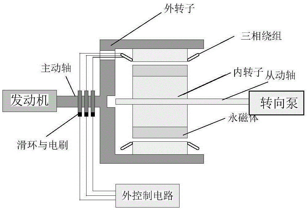
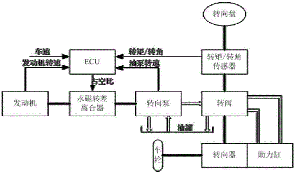
[0052] Step 1: Build a permanent magnet slip clutch type electronically controlled hydraulic power steering system

[0053] Such as figure 1 , As shown in 2, the permanent magnet slip clutch is mainly composed of an outer rotor, an inner rotor and an outer control circuit. The outer rotor is embedded with three-phase windings, which are connected to the external control circuit through slip rings and brushes, and the inner rotor is surface-attached with permanent magnets to form a hidden pole inner rotor structure. The outer rotor is the input end, which is connected to the engine through the driving shaft, and the inner rotor is the output end, which is connected to the steering pump through the driven shaft, thus for...