[0029] The technical solutions of the present invention are described in detail below, but the protection scope of the present invention is not limited to the embodiments.
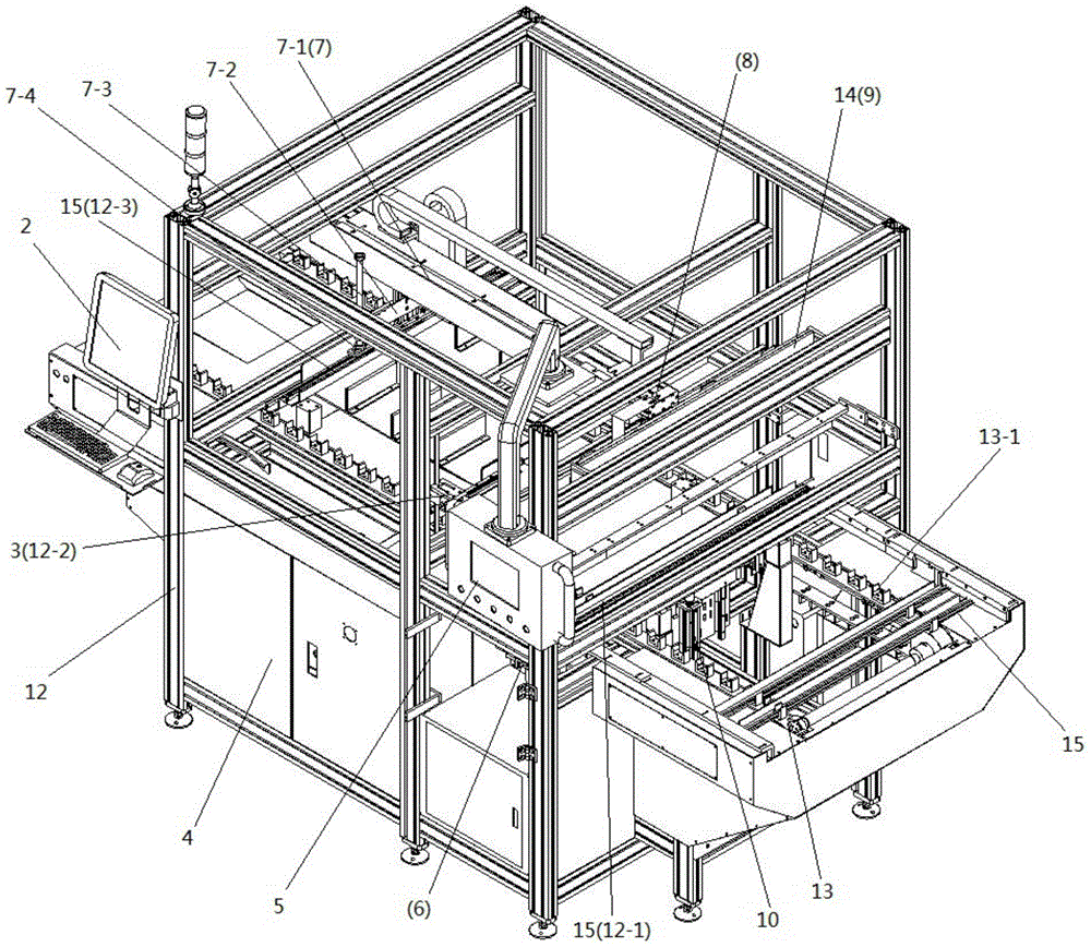
[0030] In order to make the content of the present invention more obvious and easy to understand, the following is combined with the appendix figure 1 and specific implementations for further description.
[0031] In order to make the objectives, technical solutions and advantages of the present invention clearer, the present invention will be further described in detail below with reference to the accompanying drawings and embodiments. It should be understood that the specific embodiments described herein are only used to explain the present invention, but not to limit the present invention.
[0032] An automatic detection device of the present invention includes an equipment rack 12, and the equipment rack 12 is divided into a lower main control cabinet unit 4 and an upper working unit; the lower main control cabinet unit 4 is provided with a main controller, a detection data display 2 and an operation unit. The control panel 5; the detection data display 2 and the operation control panel 5 are respectively connected to the main controller. The main controller, the detection data display 2 and the operation control panel 5 used in this embodiment are all conventional technical products in the prior art.
[0033]A workbench is set on the equipment rack 12 located in the upper working unit. The two ends of the workbench are the feed end and the discharge end respectively, and the workbench is provided with detection stations 12- 1. The coding station 12-2 and the defective products are moved out of the station 12-3. The worktable is provided with a feeding conveyor belt 13 that moves along the length of the worktable. In this embodiment, a detection station 12-1, a coding station 12-2 and a defective product removal station 12-3 are sequentially set on the worktable from the feed end to the discharge end; The setting is used to collect the detection information of the workpiece 15 to be tested. The setting of the coding station 12-2 is used to print the qualified products according to the needs of the customer. Types of products are removed and defective products are classified and framed. In this embodiment, the feeding conveyor belt 13 is provided with positioning grooves 13-1 for placing workpieces to be detected, and the positioning grooves 13-1 are uniformly arranged. In the technical solution of this embodiment, a position sensor at the discharge end for detecting whether the qualified product located on the discharge end is taken away is connected to the main controller.
[0034] On the equipment rack 12 located in the upper working unit, a collector is provided at the detection station 12-1 for collecting the detection data of the workpiece 15 to be detected. The collector includes a collector arranged on the equipment rack 12 for collecting the detection data. The first camera 6 for collecting data at both ends of the workpiece 15 , and no less than one second camera 9 , which is installed on the equipment rack 12 through the collector mounting bracket 14 and located above the workpiece 15 to be detected, is installed on the equipment rack 12 And no less than one third acquisition camera 8 located on the same plane as the workpiece 15 to be detected and not less than one fourth acquisition camera mounted on the equipment rack 12 and located below the workpiece 15 to be detected; the first acquisition camera 6 , the second acquisition camera 9 , the third acquisition camera 8 and the fourth acquisition camera are respectively connected to the main controller and to the detection data display 2 respectively. This embodiment figure 1 The first capture camera 6 , the second capture camera 9 , the third capture camera 8 and the fourth capture camera are not shown, but their respective installation positions are only schematically shown.
[0035] On the equipment rack 12 located in the upper working unit, a jacking cylinder 10 is provided at the inspection station 12-1 for transporting the workpiece 15 to be inspected to the collector, and the shell of the jacking cylinder 10 is installed on the equipment machine. On the frame 12 and the piston rod contacts the workpiece 15 to be inspected at the inspection station 12-1. The jacking cylinder 10 in this embodiment adopts a conventional cylinder in the prior art.
[0036] On the equipment rack 12 in the upper working unit, an ink jet 3 is set at the coding station 12-2, and the ink jet 3 is installed on the equipment rack 12 and located below the workpiece 15 to be inspected. The inkjet printer 3 in this embodiment adopts the conventional inkjet printer in the prior art, and the inkjet printer 3 can ink the required code according to the customer's requirements.
[0037] On the equipment rack 12 located in the upper working unit, a defective product removing mechanism 7 is provided at the defective product removing station 12-3. The defective product removal mechanism 7 includes a beam 7-1 arranged on the equipment rack 12 and the beam 7-1 is arranged along the length direction of the workbench; a connecting plate 7-2 is arranged below the beam 7-1 and the connecting plate 7-2 can slide up and down , the connecting plate 7-2 slides along the length direction of the beam 7-1, the two ends of the connecting plate 7-2 are respectively provided with a cylinder 7-3, and the piston rod of the cylinder 7-3 is provided with a suction cup 7-3 for sucking defective products 4. The connecting plate 7-2 is arranged on the beam 7-1 through the sliding connecting shaft, and the connecting plate 7-2 slides up and down along the sliding connecting shaft; the sliding connecting shaft and the beam 7-1 are connected by the slider and the chute. The connecting plate 7-2 slides along the length direction of the beam 7-1.
[0038] A centralized dust cover ( figure 1 (not shown in the figure), which effectively guarantees the accuracy of the automatic detection equipment.
[0039] The working process of the present invention:
[0040] The worker who checks the appearance puts the workpiece to be tested after the appearance is checked into the positioning slot of the feeding conveyor belt in a certain direction, and the conveyor belt automatically sends the workpiece to be tested into the automatic testing equipment for testing. When the workpiece to be inspected is transported to the inspection station 12-1, the lifting cylinder 10 transports the workpiece to be inspected 15 to the collector, the first acquisition camera 6, the second acquisition camera 9, the third acquisition camera 8 and the fourth acquisition camera At the same time, the camera takes pictures and collects the workpiece 15 to be inspected, and transmits the collected information to the main controller and the inspection data display 2 in real time; The information is compared with the parameters set in the main controller; after the inspection, the qualified products are automatically placed on the feeding conveyor belt, and transported by the feeding conveyor belt to the coding station 12-2, which is located in the coding station 12 -2 out of the inkjet printer 3 automatically sprays different codes according to customer requirements; after the coding is completed, it is output from the feeding conveyor belt to the end of the conveyor belt, and the qualified products are taken from the discharging end. After testing, when it is found that it is a defective product, it is determined which type of defective product it is, and then the defective product is automatically placed on the feeding conveyor belt, and is transported by the feeding conveyor belt 3 to the coding station 12-2. In the coding station 12-2, the coding process is not performed, and it continues to be transported to the next process, and the defective products are removed by the defective product removal mechanism 7 and placed in the corresponding defective product frame.