Fine tail yarn eliminator

A technology of clearing machine and fine tail yarn, which is applied in the direction of conveying filamentous materials, thin material processing, transportation and packaging, etc., and can solve problems such as labor-intensive, time-consuming and labor-intensive

Inactive Publication Date: 2016-05-25
崔斌
View PDF0 Cites 6 Cited by
  • Summary
  • Abstract
  • Description
  • Claims
  • Application Information

AI Technical Summary

Problems solved by technology

labor-intensive, time-consuming, labor-intensive

Method used


Image

  • Fine tail yarn eliminator
  • Fine tail yarn eliminator
  • Fine tail yarn eliminator

Examples


Embodiment Construction

[0028] The patent of the present invention will be described in more detail below with reference to the accompanying drawings.

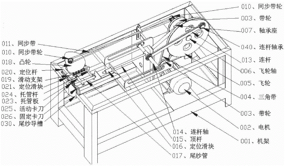
[0029] When the fine tail yarn needs to be removed, such as figure 1 As shown, press the power button 031, turn on the power, and then start the work button 032, the motor 002, and work.

[0030] Put the tail yarn bobbin 017 to be removed into the tail yarn tube guide groove 030 and the upper opening in different sizes.

[0031] The motor 002, through the pulley 003, the V-belt 004, is driven to the flywheel shaft 006 and the flywheel 005 installed in the frame 001, the middle, and rotates.

[0032] One end of the connecting rod 013 is installed on the other side of the flywheel 005 through the connecting rod bearing 040, and also rotates accordingly.

[0033] The connecting rod 013, the other end is installed on the connecting rod shaft 014, which slides back and forth through the connecting rod bearing 040, and the connecting rod shaft 014, both ...


PUM


Abstract

The invention relates to a fine tail yarn eliminator and belongs to the technical field of spinning machines of textile equipment. The equipment comprises an independent fine tail yarn eliminator consisting of a rack, a power control system, a flywheel connecting rod device, a bobbin conveying device, a yarn stripping device, an auxiliary drive mechanism and the like. The fine tail yarn eliminator can be used for realizing automatic fine tail yarn elimination working process. The fine tail yarn eliminator provided by the patent of the invention is capable of replacing manpower to automatically eliminate tail yarns reserved on hollow bobbins, alleviating the labor intensity and the worker quantity and improving the production efficiency.

Description

technical field [0001] The patent of the invention belongs to the field of textile equipment, and in particular relates to a fine tail yarn removing machine, which replaces the manual automatic stripping of empty yarn bobbins to leave tail yarns. Background technique [0002] At present, the method of removing the slender yarn is mainly to cut the yarn manually with a hook knife. Labor, time, and effort. SUMMARY OF THE INVENTION [0003] In order to overcome the above-mentioned deficiencies of the prior art, the purpose of the patent of the present invention is to provide a brand-new automatic slender tail yarn removal device. Easy to use, just put the bobbin with the fine tail yarn on the fine tail yarn removing machine of the present invention, and start the work button, the fine tail yarn removal can be automatically completed, and has the characteristics of high speed and good stability. Improve the automatic continuous production level of manufacturers. At the same...

Claims


Application Information

Patent Timeline
Patent Type & Authority Applications(China)
IPC IPC(8): B65H73/00
CPCB65H73/00
Inventor 崔斌
Owner 崔斌
Why Eureka
Try Eureka