Vacuum evaporation heating device

A heating device and vacuum technology, which is applied in vacuum evaporation plating, sputtering plating, ion implantation plating, etc., can solve the problems that are not conducive to reducing the frequency of opening cavity and refueling and other machine maintenance items, the horizontal and radial temperature of the crucible Poor, not conducive to production efficiency and other issues, to achieve the effect of simple structure, improve production efficiency, and prevent hole plugging

Active Publication Date: 2016-05-25
TCL CHINA STAR OPTOELECTRONICS TECH CO LTD
View PDF4 Cites 12 Cited by
  • Summary
  • Abstract
  • Description
  • Claims
  • Application Information

AI Technical Summary

Problems solved by technology

At present, there is no special technology to solve the problem of the horizontal and radial temperature difference of the crucible. It is also due to the limitation of the horizontal and radial temperature difference that the diameter of the crucible cannot be made larger, because the larger the diameter of the crucible, the greater the radial temperature difference. , the easier it is to plug holes
This limits the amount of material placed in the crucible, which is not conducive to reducing the frequency of refilling and other machine maintenance, which is not conducive to the improvement of production efficiency.

Method used


Image

  • Vacuum evaporation heating device
  • Vacuum evaporation heating device
  • Vacuum evaporation heating device

Examples


Embodiment Construction

[0026] In order to further illustrate the technical means adopted by the present invention and its effects, the following describes in detail in conjunction with preferred embodiments of the present invention and accompanying drawings.

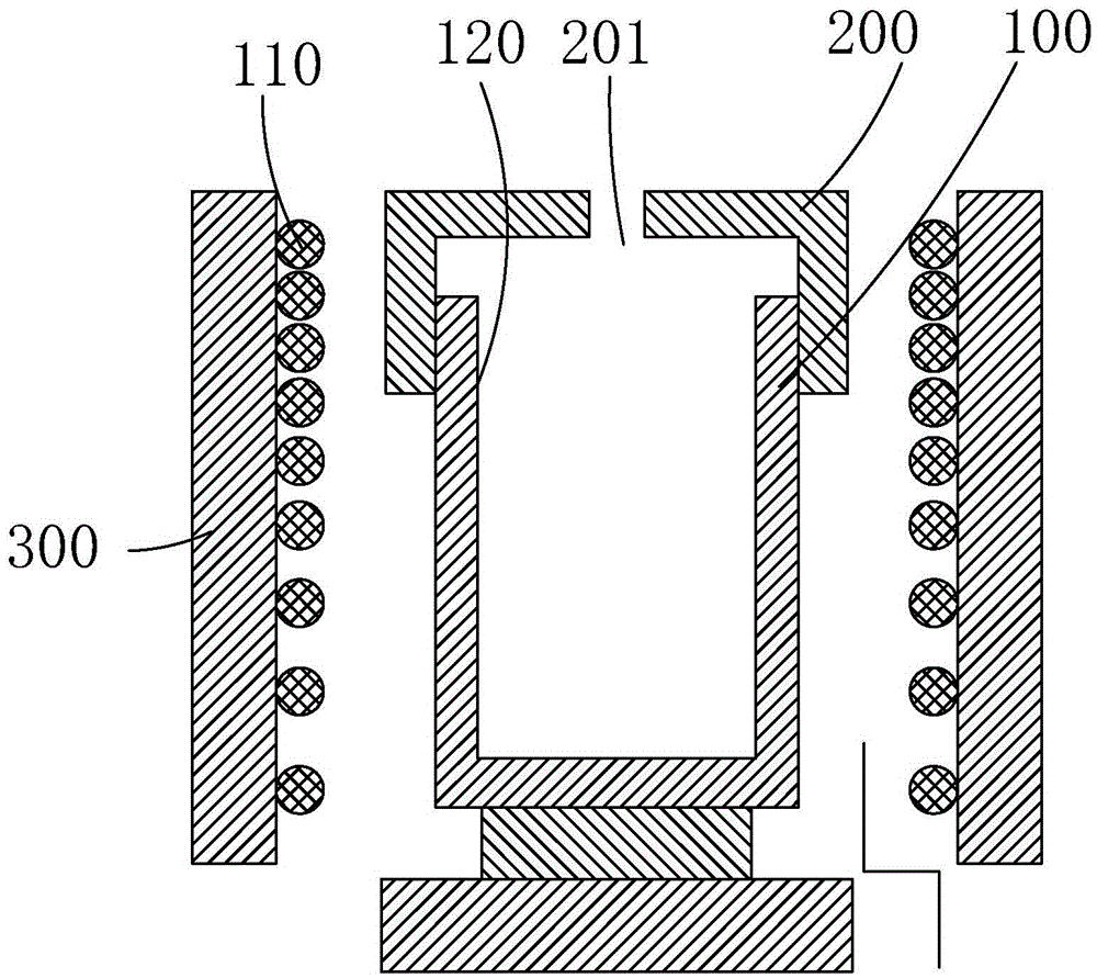
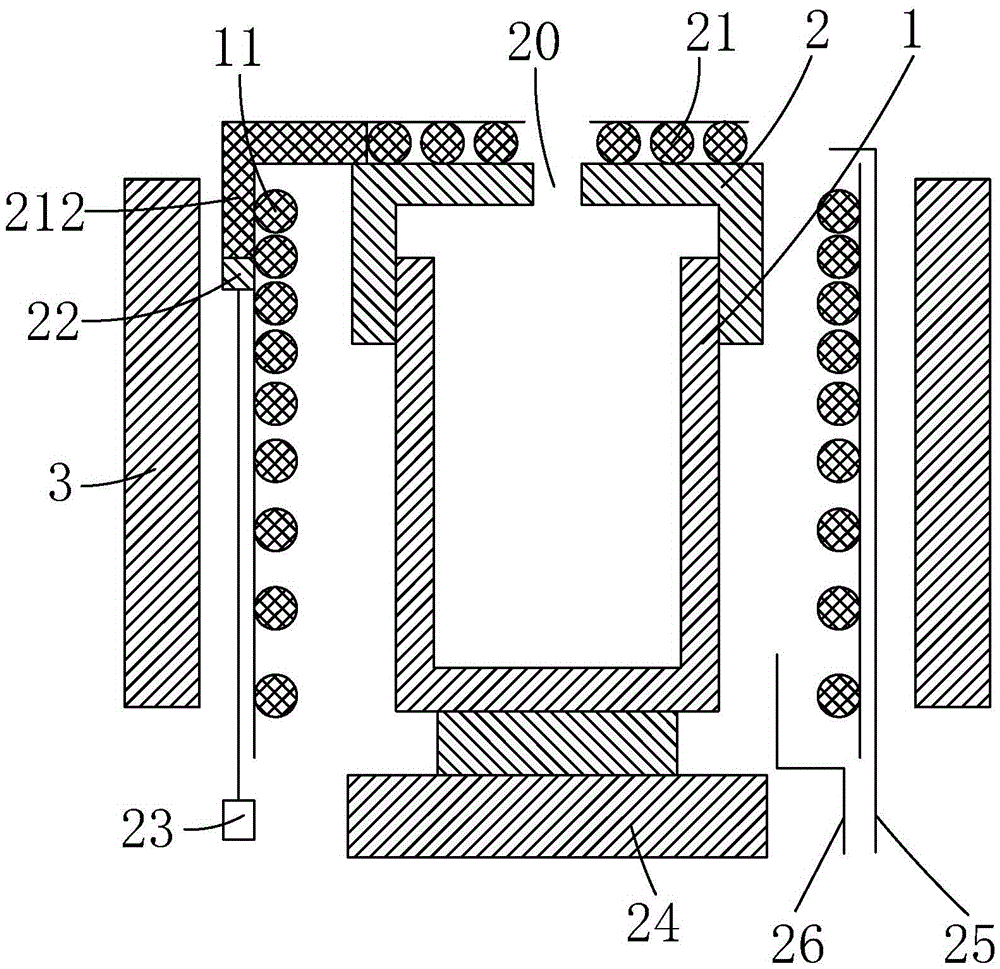
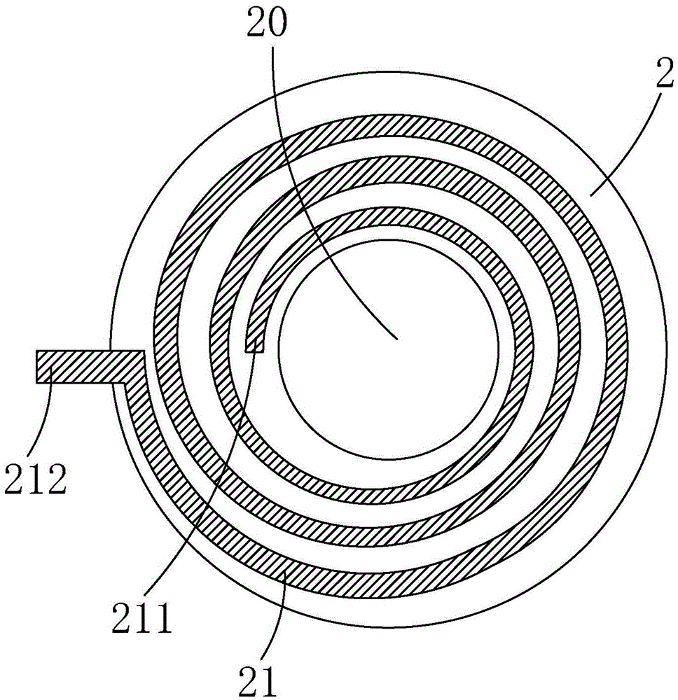
[0027] see Figure 2 to Figure 4 , The present invention provides a heating device for vacuum evaporation, comprising an outer wall 3 of the heating device, a crucible 1 disposed inside the outer wall 3 of the heating device, and a crucible cover 2 disposed on the crucible 1 .

[0028] Specifically, a first heating coil 11 is provided between the crucible 1 and the outer wall 3 of the heating device corresponding to the peripheries of the crucible 1 and the crucible cover 2 . The center of the crucible cover 2 is provided with a nozzle 20 penetrating through the upper and lower surfaces of the crucible cover 2, which is used to fly vaporized evaporation material molecules from the nozzle 20 to deposit on the substrate to form a solid film duri...


PUM


Abstract

The invention provides a vacuum evaporation heating device. The vacuum evaporation heating device comprises a heating device outer wall (3), a crucible (1) arranged inside the heating device outer wall (3) and a crucible cover (2) arranged on the crucible (1), wherein a first heating coil (11) is arranged at the periphery corresponding to the crucible (1) and the crucible cover (2) between the crucible (1) and the heating device outer wall (3); a nozzle (20) penetrating the upper surface and the lower surface of the crucible cover (2) is formed in the center of the crucible cover (2), and a second heating coil (21) is arranged at the periphery corresponding to the nozzle (20) on the crucible cover (2); and the first heating coil (11) and the second heating coil (21) are respectively electrically connected with a power supply and can be individually controlled for carrying out heating. The vacuum evaporation heating device has the advantages that horizontal radial temperature difference of the crucible can be effectively reduced, hole is prevented from being blocked by material, diameter can be designed to be larger, material placing amount is increased, cavity opening frequency is reduced, and production efficiency is improved; and structure is simple, and the vacuum evaporation heating device is easy to produce.

Description

technical field [0001] The invention relates to the field of display technology, in particular to a vacuum evaporation heating device. Background technique [0002] Organic Light-Emitting Diode (OLED) is known as the next-generation display technology, which has excellent display performance, especially self-illumination, simple structure, ultra-thin, fast response, wide viewing angle, low power consumption and flexible display properties. At present, the mass-produced OLED manufacturing technology adopts the method of vacuum evaporation to prepare OLED material thin films. [0003] During evaporation in the vacuum evaporation chamber, the material is placed in the crucible, and the crucible is placed in the heating device. When heated to the evaporation temperature, the material is vaporized, and the vaporized molecules fly out from the nozzle of the crucible cover and deposit on the substrate to form a solid film. If the temperature is not properly controlled and the tem...

Claims


Application Information

Patent Timeline
Patent Type & Authority Applications(China)
IPC IPC(8): C23C14/26
CPCC23C14/26C23C14/12C23C14/243H10K71/164H10K71/00C23C14/54
Inventor 刘扬刘亚伟
Owner TCL CHINA STAR OPTOELECTRONICS TECH CO LTD
Why Eureka
Try Eureka