
Air dense medium dry separation device

An air heavy mediating and sorting technology, which is used in wet separation, grading, and separation of solids from solids by air flow. And other issues

Inactive Publication Date: 2011-05-11
孙刚
View PDF8 Cites 7 Cited by
  • Summary
  • Abstract
  • Description
  • Claims
  • Application Information

AI Technical Summary

Problems solved by technology

With this kind of scraper machine 5 and air distribution device 8, since the scraper directly scrapes over the air distribution plate, not only the small holes are easily blocked by the falling fine-grained materials and media, but also the scraper will further remove the fine-grained materials and media. It is stuck in the small holes, and the uneven accumulation of materials passing through the scraper affects the air distribution and fluidization effects, and it is easy to form a dead bed, which further affects the separation effect, and it is very difficult to realize industrial application.
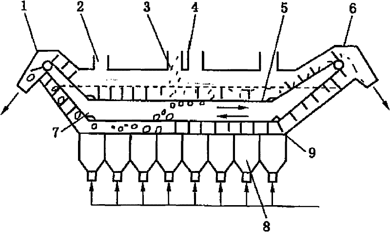
[0005] Moreover, since the scraper machine used in the traditional air-dense medium separation equipment is a straight scraper connected by anchor chains, during the process of discharging the sunken objects, the scraper rubs against the air distribution plate and blows over. The fine-grained materials and media of the sediment will be blocked in the small holes of the air distribution plate, resulting in blockage of the small holes, and it is difficult for the air flow to be discharged from the air distribution plate smoothly, so that a uniform and stable sorting fluidized bed cannot be formed
[0006] In addition, because the materials and media will accumulate at the bottom of the scraper after falling, this accumulation will cause difficulty in the movement of the scraper and deformation and fracture of the scraper

Method used


Image

  • Air dense medium dry separation device
  • Air dense medium dry separation device
  • Air dense medium dry separation device

Examples


Embodiment Construction

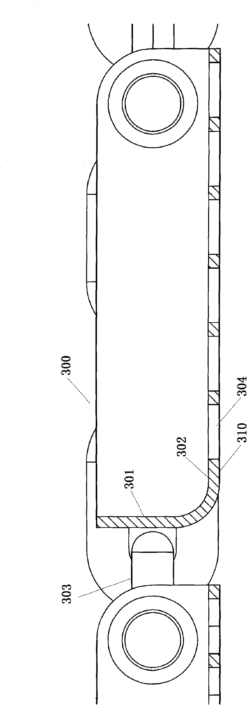
[0022] Such as figure 2 , 3 , 4, the air dense medium dry separation equipment of the present invention includes: a box 100, a pallet device 300, and an air distribution device 400. The box body 100 is used for providing a space for forming a sorting fluidized bed and for installing a pallet device and an air distribution device. The sorting fluidized bed is a laminar fluid formed when air, heavy medium and other substances pass through the air distribution device 400 . The air distribution device 400 is located at the lower part of the box body. The supporting plate device 300 is used to transport floating and sinking objects, which are formed when the materials to be sorted pass through the sorting fluidized bed and the air distribution device, and the supporting plate device is located above the air distribution device. The pallet device includes a plurality of pallets or screens that are linked, and the multiple pallets or screens that are linked circulate around two r...


PUM

PropertyMeasurementUnit
Heightaaaaaaaaaa
Granularityaaaaaaaaaa

Abstract

The invention discloses an air dense medium dry separation device, comprising: a box body, a supporting plate device and an air distribution device, wherein the box body is used for providing a space for forming a separation fluidized bed and is further used for installing the supporting plate device and the air distribution device; the air distribution device is arranged at a lower part of the box body; the supporting plate device is used for conveying floats and sediments, the floats and sediments are formed in a process when materials pass through the separation fluidized bed and the air distribution device, the supporting plate device is located over the air distribution device and comprises a plurality of linked supporting plates or screens circularly operating around two rotation shafts, each supporting plate or screen comprises a baffle part which is vertical to a bed layer surface of the separation fluidized bed, and a flat plate part which is connected with the baffle part and is parallel to the bed layer surface, and the flat plate part comprises through holes or meshes. According to the device disclosed in the invention, a problem of failure in fluidization and separation caused by blockage of air holes is effectively avoided.

Description

technical field [0001] The invention relates to mineral separation equipment, in particular to a separation equipment using air-dense medium dry method. Background technique [0002] Among the coal preparation technologies, the air-dense medium dry separation technology has attracted extensive attention from all over the world because it can be effectively used in arid and water-scarce areas. [0003] In the prior art, the equipment for sorting by air-dense medium dry method usually includes feed inlets 3 and 4, air distribution device 8, scraper machine 5 and discharge outlets 1 and 6, such as figure 1 shown. The raw material to be selected is sent in from the feed port 4, and the air distribution device 8 at the bottom of the bed sends air to the weight and material through the air distribution device. According to Archimedes' principle, the material flows in the fluidized dense air The fluidized bed 7 is layered according to the density, and at the same time, under the ...

Claims


Application Information

Patent Timeline
IPC IPC(8): B03B5/46B07B13/04B07B11/06
Inventor 孙刚吴玲孙峥
Owner 孙刚
Learn More