
Bridge abutment structure capable of preventing bumping at bridge head and preventing method

A bridge head jumping and abutment technology, which is applied to bridges, bridge parts, bridge maintenance and other directions, can solve problems such as height difference, bridge head jumping, settlement difference, etc., to achieve simple structure design, prevent bridge head jumping, and eliminate bridge head. The effect of differential settlement

Inactive Publication Date: 2016-05-25
CHANGAN UNIV
View PDF6 Cites 6 Cited by
  • Summary
  • Abstract
  • Description
  • Claims
  • Application Information

AI Technical Summary

Problems solved by technology

There are differences in the composition materials, stiffness, strength, and expansion and contraction of bridges, roadbeds, and road surfaces, and concentrated stress is easily formed when the bridgehead connection is stressed. Under the action of vehicle loads, structural weight, and natural factors, bridges and roads simultaneously settle , but the settlement of the two is very different. The settlement of the road is much greater than the settlement of the bridge, forming a staggered platform. The height difference between the bridge and the back wall on the reinforced concrete pendulum support causes the bridge head to jump when driving. car

Method used


Image

  • Bridge abutment structure capable of preventing bumping at bridge head and preventing method
  • Bridge abutment structure capable of preventing bumping at bridge head and preventing method
  • Bridge abutment structure capable of preventing bumping at bridge head and preventing method

Examples


Embodiment 1

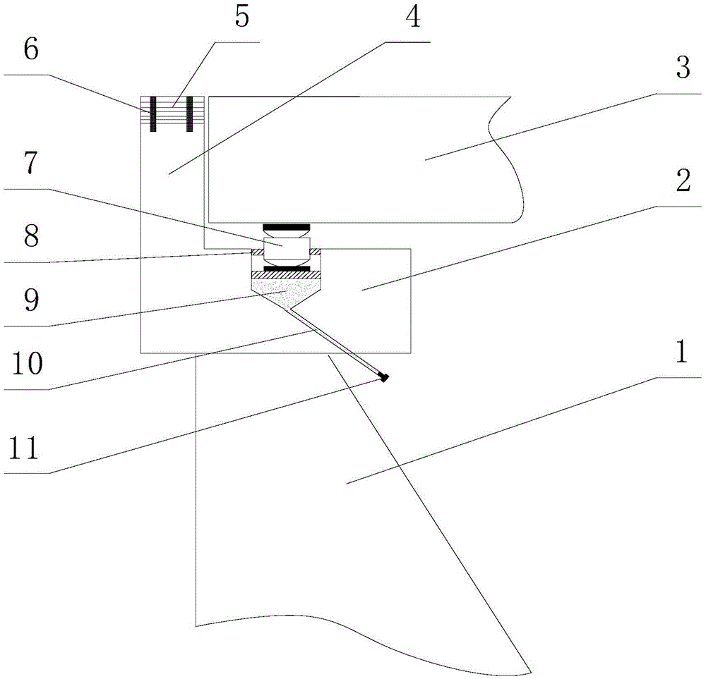
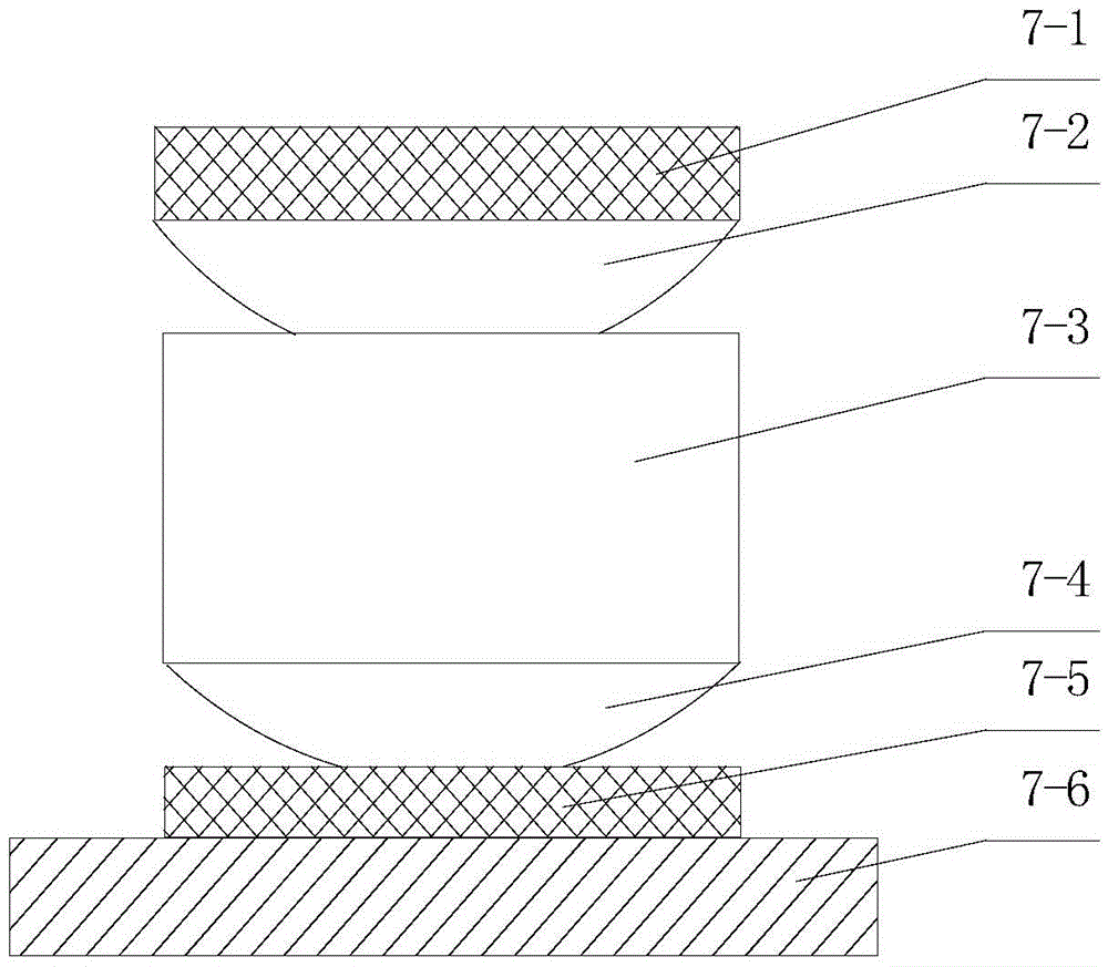
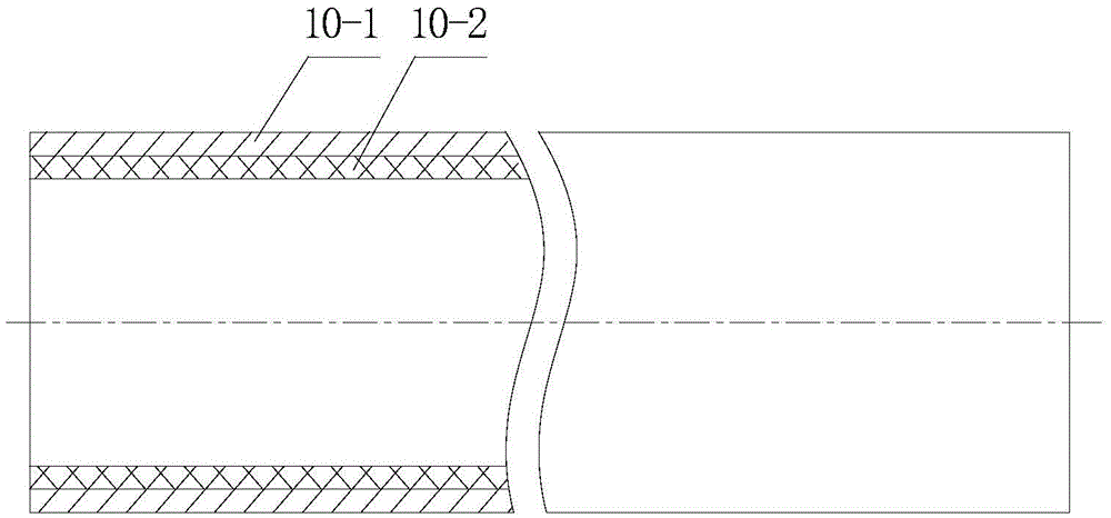
[0022] Depend on figure 1 It can be seen that the abutment structure of the present embodiment that can prevent vehicle jumping at the bridge head is composed of platform cap 2, back wall 4, adjustment plate 5, adjustment anchor bolt 6, sand 9, pendulum type support 7, elastic filling layer 8, row The sand pipe 10 and the plug 11 are combined.

[0023] The abutment of this embodiment is located at the end of the bridge 3, the abutment is made up of a platform cap 2 and a back wall 4, the platform cap 2 is horizontally installed on the pier 1, and the back wall 4 is vertically installed on one side of the platform cap 2, for It is convenient to adjust the height of the back wall 4. On the top of the back wall 4, 10 layers of steel plates are stacked as the adjustment plate 5. The thickness of each layer of the adjustment plate 5 is 4cm, and the length and width are the same as the size of the back wall 4. On the adjustment plate 5, there are screw hole, and pass the screw hole...

Embodiment 2

[0030] The abutment of this embodiment is located at the end of the bridge 3, the abutment is made up of a platform cap 2 and a back wall 4, the platform cap 2 is horizontally installed on the pier 1, and the back wall 4 is vertically installed on one side of the platform cap 2, for It is convenient to adjust the height of the back wall 4. On the top of the back wall 4, 5 layers of steel plates are laminated as the adjustment plate 5. The thickness of each layer of adjustment plates 5 is 5 cm, and the length and width are the same as the size of the back wall 4. In order to ensure smooth sand discharge , An included angle of 20° is formed between the central axis of the sand discharge pipe 10 and the central axis of the borehole.

[0031] In order to prevent the pendulum support 7 from tilting left and right in the well, the gap between the pendulum support 7 and the inner wall of the well is filled with an elastic filling layer 8. The elastic filling layer 8 can be made of rub...

Embodiment 3

[0037] The abutment of this embodiment is located at the end of the bridge 3, the abutment is made up of a platform cap 2 and a back wall 4, the platform cap 2 is horizontally installed on the pier 1, and the back wall 4 is vertically installed on one side of the platform cap 2, for It is convenient to adjust the height of the back wall 4. On the top of the back wall 4, 6 layers of steel plates are stacked as the adjustment plate 5. The thickness of each layer of the adjustment plate 5 is 3cm, and the length and width are the same as the back wall 4. In order to ensure smooth sand discharge , An included angle of 60° is formed between the central axis of the sand discharge pipe 10 and the central axis of the borehole.

[0038] In order to prevent the pendulum support 7 from tilting left and right in the well, the gap between the pendulum support 7 and the inner wall of the well is filled with an elastic filling layer 8. The elastic filling layer 8 can be made of rubber or Polyet...


PUM


Abstract

The invention relates to a bridge abutment structure capable of preventing bumping at a bridge head and a preventing method. The bridge abutment structure comprises an abutment cap and a parados. The parados is arranged at one end of the abutment cap and is perpendicular to the abutment cap. A well hole is formed in the middle of the abutment cap, the bottom of the well hole is of a conical structure, the bottom of the well hole is filled with sand, a pendulum type support is arranged above the sand, the part between the side of the support and the inner wall of the well hole is filled with an elastic padding layer, a sand discharging pipe is arranged in a sand discharging port in the bottom of the well hole, an end cap is arranged in the port of the sand discharging pipe, and an adjusting plate is arranged on the top of the parados in an overlapped mode. Uniform settlement of a bridge surface is achieved by adjusting the height of the support and the elevation of the parados of the bridge abutment, differential settlement of the bridge head is eliminated, the bumping phenomenon caused by sedimentation of a bridge head embankment can be conveniently eliminated, the structural design is simple, and adjustment is convenient; original using function of a bridge are not affected, and the bridge abutment structure can be used for an old and new bridge structure of a municipal administration highway, and can also be used for track traffic projects.

Description

technical field [0001] The invention belongs to the technical field of bridge engineering, and in particular relates to an abutment structure capable of eliminating vehicle jumping at the bridge head and a prevention and control method. Background technique [0002] Since the reform and opening up, the speed of my country's highway construction has been advancing by leaps and bounds. By 2014, the mileage of my country's expressways has reached 111,950 kilometers. Bridge abutments are located at both ends of the bridge, used to support the upper structure of the bridge and connect with the embankment. Usually, the abutment is composed of a platform cap installed horizontally and a back wall installed vertically at one end of the platform cap. Pendulum bearings support the bridge. [0003] The main causes of vehicle jumping at the bridge head are: uneven settlement, sudden change in stiffness, vehicle speed and the anti-vibration performance of the vehicle itself. As far as ur...

Claims


Application Information

Patent Timeline
Patent Type & Authority Applications(China)
IPC IPC(8): E01D19/02E01D19/04E01D21/00E01D22/00
CPCE01D19/02E01D19/043E01D21/00E01D22/00
Inventor 李蕊邹道光裴建中朱红斌张久鹏崔节雪石志梁
Owner CHANGAN UNIV
Learn More