Peg and plate shell structure for controlling deformation of soft soil foundation under embankment

A technology for weak soil foundation and deformation control, applied in infrastructure engineering, construction, etc., can solve problems affecting driving comfort and safety, different additional stresses, uneven surface settlement, etc., to achieve small deformation and drainage consolidation Slow and low settling effect

Active Publication Date: 2014-04-09
HOHAI UNIV
View PDF4 Cites 1 Cited by
  • Summary
  • Abstract
  • Description
  • Claims
  • Application Information

AI Technical Summary

Problems solved by technology

[0003] In addition, for high-grade embankments on deep soft soil foundations, since the embankment fill load is a flexible load, it is easy to deform
Regardless of whether the drainage consolidation method or the composite foundation method is used for foundation treatment, there is a problem that the additional stress at the center of the embankment and the edge of the embankment are different. Generally, the additional stress at the center of the embankment is greater than that at the edge of the embankment, so that the settlement of the center of the embankment is larger than that of the embankment. The edge should be large, so that the surface will produce uneven settlement in the shape of "bottom of the pot", and in severe cases, it will cause longitudinal cracks in the road, which will affect the comfort and safety of driving

Method used


Image

  • Peg and plate shell structure for controlling deformation of soft soil foundation under embankment
  • Peg and plate shell structure for controlling deformation of soft soil foundation under embankment
  • Peg and plate shell structure for controlling deformation of soft soil foundation under embankment

Examples


Embodiment Construction

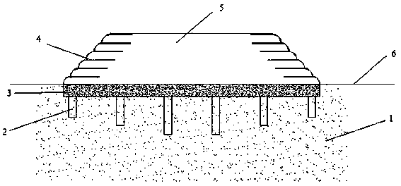
[0024] Such as figure 1 , 2 As shown in and 3, a short pile-slab shell structure controlled by the deformation of the soft soil foundation under the embankment, the construction site is first leveled, and the cushion layer is laid according to the softness and hardness of the surface soil layer to meet the requirements for the construction machinery to enter the site. Set up short piles (2) in the soft soil foundation (1). The short piles (2) are 2-5m long and the pile spacing is 3-10m. Various types of rigid piles such as X-shaped, X-shaped, Y-shaped, and cross-shaped are adopted in the form of cast-in-place or prefabricated, and cover plates are arranged on the short piles (2). The pile length of the short pile (2) can be changed, and the pile length in the middle of the embankment (5) can be longer than the pile length of the edge of the embankment (5). Since the pile is shorter, it does not penetrate the soft soil layer, and the pile end is located in the soft soil layer ...


PUM


Abstract

The invention discloses peg and plate shell structural technology for controlling deformation of a soft soil foundation under an embankment. The peg and plate shell structural technology is characterized by including steps of flattening a construction field, paving a cushion layer according to hardness of a surface soil layer, and leading the surface soil layer to be capable of bearing construction machinery; pouring pegs on the spot, or driving the prefabricated pegs into the foundation, and mounting formworks on the edges of the embankment; placing a reinforcement cage and leading the reinforcement cage to be connected with connecting reinforcements on the pegs; pouring concrete plates; and building the embankment on the concrete plates after the concrete plates are maintained to achieve proper strength. The lengths of the pegs range from 2m to 5m, pitches among the pegs range from 3m to 10m, the pegs can be arranged in a quincunx or square manner, the thicknesses of the reinforcement concrete plates range from 30cm to 50cm, and the widths of the reinforcement concrete plates are equal to the width of the bottom of the embankment. The peg and plate shell structural technology eliminates the problem that the 'pot-bottom-shaped' differential settlement is produced on the cross section of an embankment treated by a conventional method, longitudinal cracks of the foundation are avoided, buckling failure of a slope of the foundation is also avoided, the earthwork volume of filled soil of the foundation is reduced, settlement is low after construction, work period is short, and manufacturing cost is low.

Description

technical field [0001] The invention belongs to the technical field of civil engineering, and in particular relates to a short pile-plate shell structure for controlling the deformation of soft ground under embankments. Background technique [0002] my country is carrying out large-scale infrastructure construction, and most of the engineering construction is located in the soft soil areas of my country's coastal and inland lakes. In the construction of highways, high-speed railways, river embankments, etc. on weak soil foundations, it is necessary to treat the weak soil foundations to control post-construction settlement. For high-grade embankments, post-construction settlement is defined as the settlement within 15 years after the completion of road construction. According to the "Code for Design of Highway Subgrade" (JTGD30-2004), the post-construction settlement of the bridge head section is controlled at 10cm, and the post-construction settlement of the bridge head tran...

Claims


Application Information

Patent Timeline
Patent Type & Authority Patents(China)
IPC IPC(8): E02D27/12E02D27/14E02D27/34
Inventor 刘汉龙庄妍丁选明沈扬李平
Owner HOHAI UNIV
Why Eureka
Try Eureka