A slider switching device and a shutter rope reel using the device

A switching device and slider technology, applied in door/window protection devices, windows/doors, shading screens, etc., can solve the problems of difficult operation, unevenness at both ends of the bottom rail, inaccurate determination, etc. The switching is flexible and smooth, and the effect of accelerating the wear of the mechanism

Active Publication Date: 2017-08-25
杭州霏派遮阳科技有限公司
View PDF3 Cites 2 Cited by
  • Summary
  • Abstract
  • Description
  • Claims
  • Application Information

AI Technical Summary

Problems solved by technology

[0003] Although the existing shutter rope winding mechanism that adopts planetary gear clutches and screw rods and nut slider mechanisms can better solve the problem that the moving parts are not easy to break away from the planetary wheel carrier cam, the nut slider is pushing the slider away from the planetary wheel carrier cam. During the process, it will be locked on the wall of the base gradually. When the nut slider returns, it often needs to be operated with a large force, which is easy to cause thread wear and tooth slippage, so that the operation becomes more difficult after long-term use. In addition, the rope reels at both ends of the top rail of the shutter The initial position of the nut slider on the screw rod is determined inaccurately, which may easily lead to unevenness at both ends when the bottom rail rises and falls when the blades are retracted. Slider switching device and shutter rope reel using the device

Method used


Image

  • A slider switching device and a shutter rope reel using the device
  • A slider switching device and a shutter rope reel using the device
  • A slider switching device and a shutter rope reel using the device

Examples


Embodiment Construction

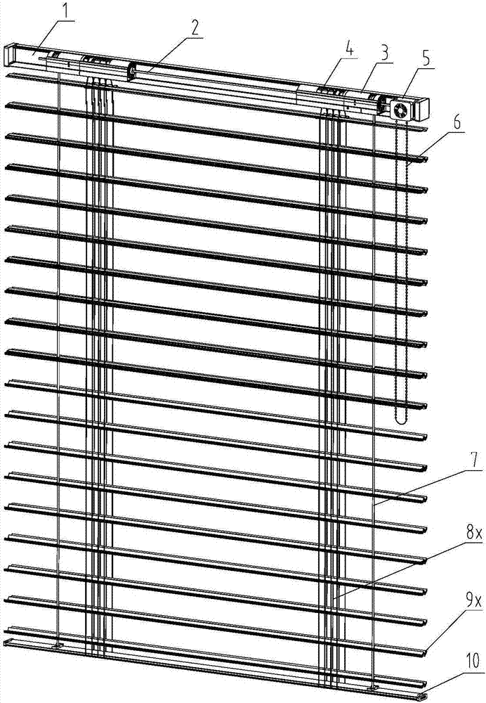
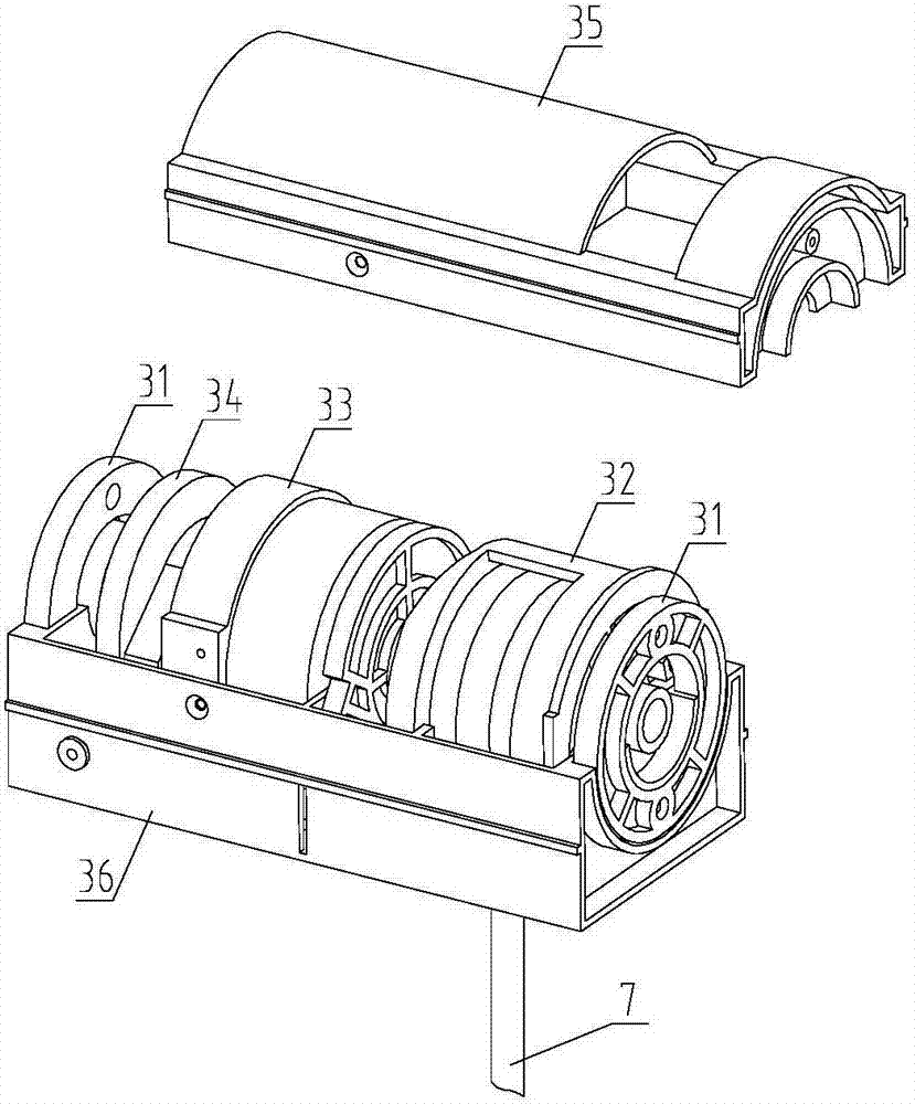
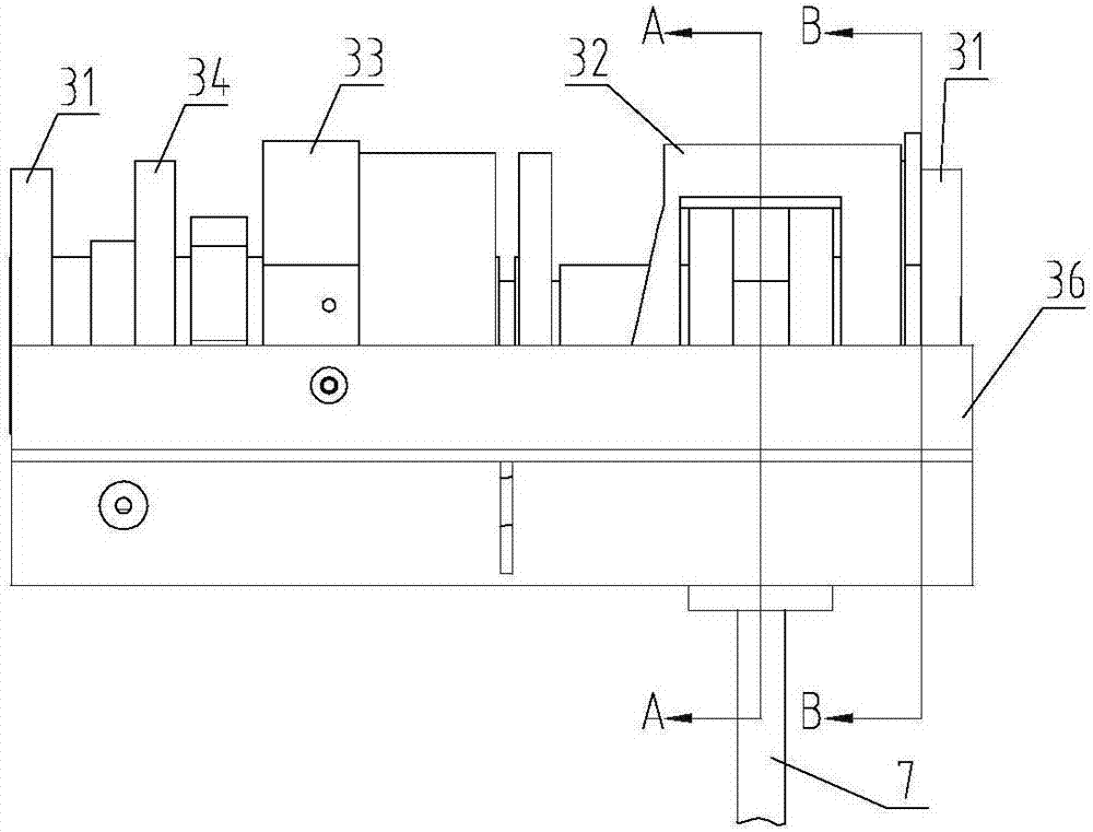
[0036] figure 1 A 3D drawing of a shutter is shown, the shutter consists of a top rail 1, a drive shaft 2, a transmission mechanism, a lift rope 7, a ladder belt 8x, blades 9x and a bottom rail 10, the transmission mechanism is placed in the top rail, the transmission mechanism is provided by a drive shaft 2 , several rope reels 3 with switching devices, several lifting and turning devices 4 and drivers 5, the drive shaft 2 passes through the drivers 5 and the rope reels 3 and lifting and turning devices 4 with switching devices, and pulls the beads of the drivers 5 The chain 6 makes the driver 5 rotate to drive the drive shaft 2 to rotate, and the drive shaft 2 drives the rope reel 3 with switching device and the lifting flipper 4 to rotate, and the rope reel 3 drives the bottom rail 10 to rise and fall through the lifting rope 7 wound on it To gather and open the blades, the lifting flipper 4 controls the relative lifting and flipping of the blades 9x through the ladder belt...


PUM


Abstract

The invention discloses a sliding block switching device. The sliding block switching device comprises a base, a winding wheel mechanism, a speed reduction mechanism and a locking mechanism are sequentially arranged on the base, and the winding wheel mechanism and the locking mechanism are in transmission connection with the speed reduction mechanism; the locking mechanism comprises a locking cam, a swing rod and locking sliding blocks, the swing rod is hinged to the base and provided with a self-resetting mechanism, the locking sliding blocks are connected to the base in a sliding mode, the self-resetting mechanism is arranged between the locking sliding blocks and the base, a touching and pressing structure is arranged between the locking cam and the swing rod, a self-locking structure is arranged between the locking cam and the locking sliding blocks, and the winding wheel mechanism and the locking cam are rotationally connected to the base; the winding wheel mechanism comprises a winding wheel and an unlocking auxiliary mechanism capable of releasing self-locking of the locking cam, and the winding wheel mechanism is further provided with a winding wheel locking structure limited by the swing rod. The invention further discloses a shutter rope winder applying the sliding block switching device.

Description

technical field [0001] The invention relates to a control device on a blind and a rope winding control device using the device, in particular to a slider switching device and a blind rope winding device using the device. Background technique [0002] The switching between the louvers of the shutters being folded and opened and the blades flipping is realized through the frictional sliding between the ladder belt and the rope reel or through the torsion spring between the lifting reel of the rope reel and the blade flipping reel, such a switching method There is a defect, that is, the blades are always closed during the movement process of the shutter blades retracting and opening, which causes the lifting rope and the perforated edge of the blades to always be in a state of friction and wear quickly until they are worn off; in order to overcome this defect, the blades can be retracted Try to maintain a horizontal state during the opening process, reduce the friction between ...

Claims


Application Information

Patent Timeline
Patent Type & Authority Patents(China)
IPC IPC(8): E06B9/322E06B9/32
CPCE06B9/32E06B9/322E06B2009/3225
Inventor 张一飞许辉文
Owner 杭州霏派遮阳科技有限公司
Why Eureka
Try Eureka