
a ceiling fan

A fan and ceiling technology, applied to parts of pumping devices for elastic fluids, non-variable pumps, pump devices, etc., to achieve the effect of not being easy to move

Active Publication Date: 2017-12-19
叶志荣
View PDF9 Cites 0 Cited by
  • Summary
  • Abstract
  • Description
  • Claims
  • Application Information

AI Technical Summary

Problems solved by technology

However, in recent years, China's electrical products related to ceilings are far from keeping up with people's needs, especially the fans that are matched with ceilings are hardly available.

Method used


Image

  • a ceiling fan
  • a ceiling fan
  • a ceiling fan

Examples


Embodiment Construction

[0022] The present invention will be further described below in conjunction with the embodiments and accompanying drawings.

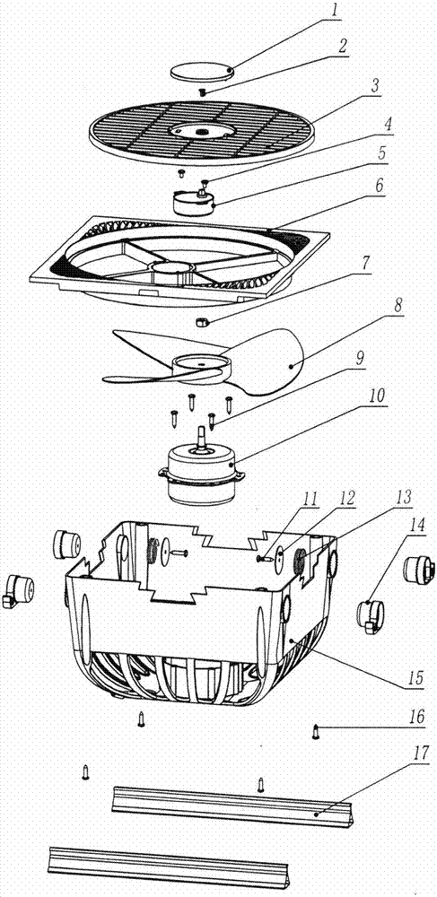
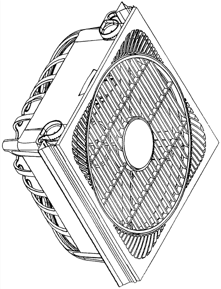
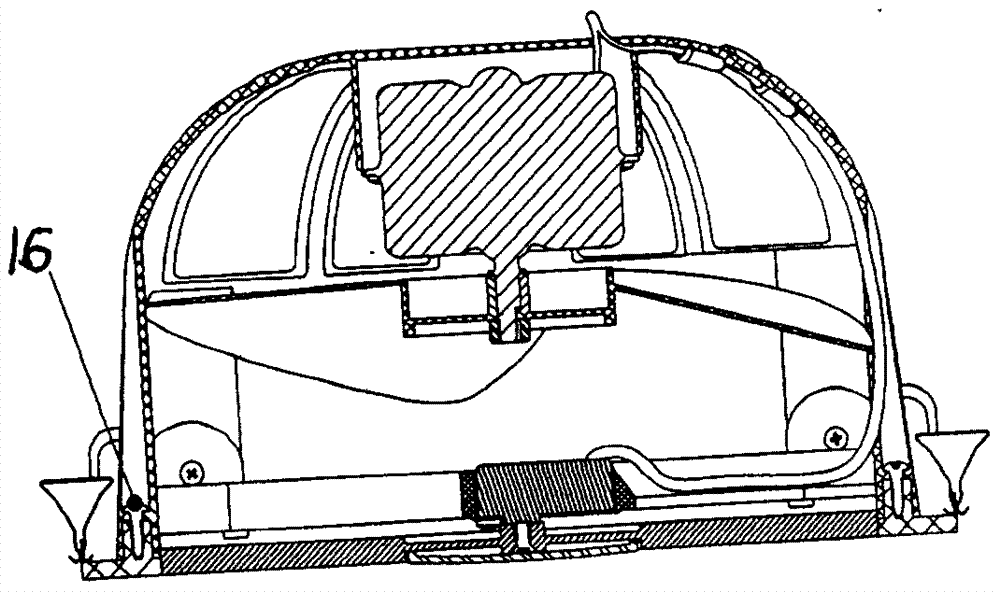
[0023] see Figure 1-Figure 3 , a ceiling fan, comprising a fan panel 6, a motor 10, fan blades 8, a fan back seat 15, two fixing clips 14 are respectively arranged on both sides of the fan back seat 15, and the two fixing clips 14 are respectively fixed on one side in each side. Keel 17 on.

[0024] see figure 1 , Figure 6-Figure 11 , the two sides of the fan back seat 15 are respectively provided with two fixing holes, the fixing holes are inserted into the fixing card 14, the fixing card 14 sets of springs 13, the gasket 12 is fixed on the fixing card 14 by the fixing card screw 11, and the spring 13 One end rests on the rear seat 15 of the fan, and the other end rests on the gasket 12. The outer periphery of the fixing hole is a gear, and the fixing card 14 is also provided with a gear step. The fixing card 14 extends into a pull hook at the gea...


PUM


Abstract

A ceiling fan comprises a fan panel, a motor, fan blades and a fan rear base. The two sides of the fan rear base are both provided with two fixing clips, and the two fixing clips in each side are fixed to a keel. Compared with the prior art, the ceiling fan has the following advantages that the two sides of the fan rear base are both provided with two fixing clips, the two fixing clips in each side are fixed to one keel, and accordingly the two keels can be conveniently installed on a standard ceiling in the existing market in a matched mode.

Description

technical field [0001] The invention relates to a fan, in particular to a ceiling fan. Background technique [0002] The integrated suspended ceiling is a combination of metal square panels and electrical appliances. Divided into heating module, lighting module and ventilation module. With simple installation, flexible layout and convenient maintenance, it has become the mainstream of bathroom and kitchen ceilings. In order to change the lack of monotonous ceiling colors, integrated art ceilings are becoming a new trend in the market. With the improvement of people's living standards, integrated ceiling aluminum gussets and related electrical products for ceilings have entered the kitchens and bathrooms of ordinary people. In the future, with the continuous improvement of integrated ceiling products, it can completely replace all architectural ceilings. However, in recent years, China's electrical products related to ceilings are far from keeping up with people's needs, ...

Claims


Application Information

Patent Timeline
Patent Type & Authority Patents(China)
IPC IPC(8): F04D25/08F04D29/00F04D29/64
CPCF04D25/088F04D29/002F04D29/646
Inventor 叶志荣
Owner 叶志荣
Learn More