
A Design Method of Single Heat Exchange Fin for LNG Vaporizer

A technology of heat exchange fins and a design method, applied in the field of LNG vaporizers, can solve the problems of not producing high-efficiency heat exchange fins, large space required for installation, reduced use efficiency, etc., and achieves reduced installation space, large safety factor, The effect of large evaporation capacity

Active Publication Date: 2015-08-05
725TH RES INST OF CHINA SHIPBUILDING INDAL CORP
View PDF1 Cites 0 Cited by
  • Summary
  • Abstract
  • Description
  • Claims
  • Application Information

AI Technical Summary

Problems solved by technology

[0003] At present, the open-frame LNG vaporizer is mostly used. The open-frame LNG vaporizer can vaporize the liquefied natural gas at about -162°C through heat exchange with the seawater outside the fins, and raise it to a normal temperature of about 2°C. The open-frame LNG vaporizer is working When the pressure is as high as 8MPa or more, all the open-frame LNG vaporizers are imported. So far, no high-efficiency heat exchange fins with a high safety factor for open-frame LNG vaporizers have been produced in China. Due to the limited evaporation capacity of the heat exchange fins, the open-frame Reduced efficiency of LNG vaporizers
[0004] Chinese patent CN201220369897.1 discloses a high-efficiency heat transfer tube for LNG vaporizer, wherein the outer finned tube has a plurality of outer fins, and a plurality of inner fins are arranged around the center hole inside the tube body, and the center of the tube body is up and down , Left and right symmetry, corrugated protrusions on the surface of the outer fins can increase the heat transfer area and strengthen the sea side heat transfer, but its evaporation capacity is small, and the space required for installation is large

Method used


Image

  • A Design Method of Single Heat Exchange Fin for LNG Vaporizer

Examples


Embodiment Construction

[0018] A single-piece heat transfer fin design method for LNG vaporizers. The single-piece heat transfer fins designed by this design method not only have a small installation space and a large evaporation capacity, but also have a high pressure bearing capacity and are safe. The coefficient is large, the heat exchange effect is good, and the freezing thickness and height of the LNG vaporizer are reduced.

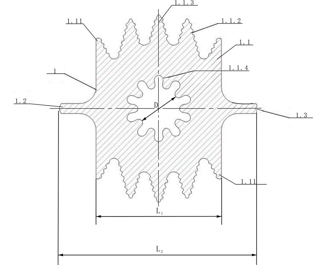
[0019] First set the width of the LNG vaporizer to be installed and positioned as L 2 And the diameter of the heat exchange pipe is D, and the single heat exchange fin 1 includes a base 1.1, an inner hole arranged on the centerline of the base, a left bracket 1.2 and a right bracket 1.3 connected to the left and right ends of the base, and the diameter of the inner hole = D.

[0020] figure 1 It is a single heat exchange finned tube with five outer fins, the present invention is not limited to figure 1 As indicated, the purpose of disclosing the invention is to protect al...


PUM


Abstract

Disclosed is a method for designing a single heat exchange fin of an LNG vaporizer. The single heat exchange fin (1) comprises a matrix (1.1), an inner hole formed in a central line of the matrix and a left support (1.2) and a right support (1.3) which are connected with the left end and the right end of the matrix. An odd number of outer fins are designed symmetrically at the upper end and the lower end of the matrix respectively, and the outer fins are in pointed-top indented shapes and subdivided into side fins (1.1.1), central fins (1.1.3) and middle fins (1.1.2). An even number of protruding grooves (1.1.4) are distributed uniformly at equal intervals in the circumferential direction of the inner hole. Compared with a prior heat exchange fin, the single heat exchange fin has the advantages that the evaporative power of the single heat exchange fin can reach 0.3t / h, mounting space required by the single heat exchange fin is reduced by 40%, the amount of seawater passing through the single heat exchange fin is reduced by 15%, the pressure bearing capacity of the single heat exchange fin is no lower than 8MPa, the security coefficient is high, the heat exchange effect is good, and the icing thickness and height of the LNG vaporizer are reduced.

Description

technical field [0001] The invention belongs to the technical field of LNG vaporizers, in particular to a design method for a single heat exchange fin used in an LNG vaporizer. Background technique [0002] Gaseous natural gas NG turns into liquid natural gas LNG after being liquefied at -162°C, and its volume can be reduced by about 620 times, which is very beneficial to reduce transportation and storage costs. However, liquid natural gas LNG must be vaporized by a vaporizer before it can be converted into gaseous natural gas. Ng. With the rapid increase in the number of LNG receiving stations in China, the market demand for LNG vaporizers is also expanding. [0003] At present, the open-frame LNG vaporizer is mostly used. The open-frame LNG vaporizer can vaporize the liquefied natural gas at about -162°C through heat exchange with the seawater outside the fins, and raise it to a normal temperature of about 2°C. The open-frame LNG vaporizer is working When the pressure is...

Claims


Application Information

Patent Timeline
Patent Type & Authority Patents(China)
IPC IPC(8): F24F1/12F17C7/04
Inventor 李培跃李士凯胡伟民
Owner 725TH RES INST OF CHINA SHIPBUILDING INDAL CORP
Learn More