Method and device for measuring pulling-out smoothness of push-in type tubular fabrics
A technology for extracting smoothness and tubular fabrics, which is applied in the direction of measuring devices, mechanical devices, instruments, etc., can solve the problems of smoothness and smoothness attenuation rate of tubular fabrics that do not involve tubular fabrics and axial friction, It does not involve problems such as the measuring device and method for the smoothness of the extraction of the tubular fabric sleeved on the heat pipe wall, and achieves the effect of simple sample clamping, simple structure, and exquisite mechanism
- Summary
- Abstract
- Description
- Claims
- Application Information
AI Technical Summary
Problems solved by technology
Method used
Image

Examples
Embodiment 1
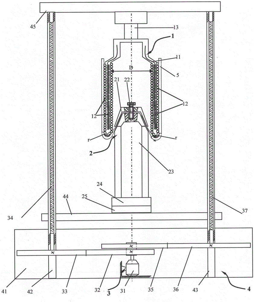
[0044] Such as figure 1 As shown, a top-entry measuring device for the smoothness of drawing tubular fabrics is composed of a heat pipe mechanism 1 , a plug mechanism 2 , a plug-plug mechanism 3 and a fixing mechanism 4 .
[0045] Described fixed mechanism 4 comprises base plate 41, left fixed rod 42, right fixed rod 43, middle beam 44 and upper beam 45, and left fixed rod 42 and right fixed rod 43 are all fixed on the base plate 41, and upper beam 45 is fixed on the left On the fixed rod 42 and the right fixed rod 43. The plug-in mechanism 3 includes a stepping motor 31, a transmission mechanism, a left screw mandrel 34 and a right screw mandrel 37, the stepping motor 31 is fixed on the base plate 41, and the left screw mandrel 34 is socketed In the left fixed rod 42 , the right screw rod 37 is sleeved in the right fixed rod 43 ; the middle beam 44 is sleeved in the left screw rod 34 and the right screw rod 37 . Described transmission mechanism comprises left driving gear 3...
Embodiment 2
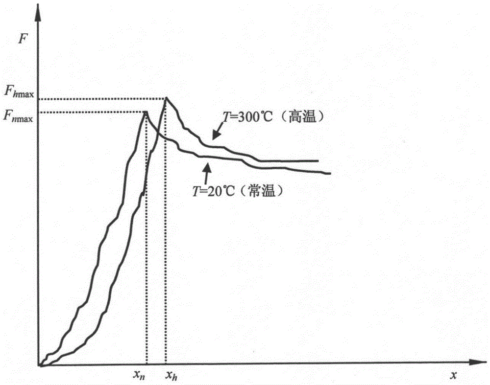
[0049] Example 2: Measurement of the pulling smoothness of high-performance tubular woven fabrics at 20°C (normal temperature)
[0050] A method for measuring the smoothness of pulling out a top-entry tubular fabric, using the top-entry measuring device for the smoothness of pulling out a tubular fabric described in Example 1, the specific steps are:
[0051] ① Select a heat pipe with a head end corner radius r of 1 mm and a cavity inner diameter D of 15 mm; select fine denier PBO weakly twisted filament yarn as raw material, and design a high-performance tubular woven fabric with a diameter of 16 mm.
[0052] ② One end of the high-performance tubular woven fabric is sleeved on the outer wall of the temperature-controllable heat pipe 11, and the other end is placed between the clamp cover 21 and the plug tube 23 and clamped by the fastening screw 22.
[0053] ③ Start the heat pipe 11, and control the temperature of the wall of the heat pipe 11 to be 20° C. (normal temperature)...
Embodiment 3
[0061] Example 3: Measurement of the pulling smoothness of high-performance tubular woven fabrics at 300°C (high temperature)
[0062] A method for measuring the smoothness of pulling out a top-entry tubular fabric, using the top-entry measuring device for the smoothness of pulling out a tubular fabric described in Example 1, the specific steps are:
[0063] ① Select a heat pipe with a head end corner radius r of 1 mm and a cavity inner diameter D of 15 mm; select fine denier PBO weakly twisted filament yarn as raw material, and design a high-performance tubular woven fabric with a diameter of 16 mm.
[0064] ② One end of the high-performance tubular woven fabric is sleeved on the outer wall of the temperature-controllable heat pipe 11, and the other end is placed between the clamp cover 21 and the plug tube 23 and clamped by the fastening screw 22.
[0065] ③ Start the heat pipe 11, and control the temperature of the wall of the heat pipe 11 to be 300° C. (high temperature). ...
PUM
| Property | Measurement | Unit |
|---|---|---|
| The inside diameter of | aaaaa | aaaaa |
| Diameter | aaaaa | aaaaa |
| Breaking strength | aaaaa | aaaaa |
Abstract
Description
Claims
Application Information
 - R&D
- Intellectual Property
- Life Sciences
- Materials
- Tech Scout
- Unparalleled Data Quality
- Higher Quality Content
- 60% Fewer Hallucinations
Browse by: Latest US Patents, China's latest patents, Technical Efficacy Thesaurus, Application Domain, Technology Topic, Popular Technical Reports.
© 2025 PatSnap. All rights reserved.Legal|Privacy policy|Modern Slavery Act Transparency Statement|Sitemap|About US| Contact US: help@patsnap.com