Pin puller applied to insulator R pin

A technology of pin pullers and insulators, applied in the direction of overhead lines/cable equipment, etc., can solve problems such as difficult to clamp, time-consuming and labor-intensive, and achieve the effect of time-consuming and labor-intensive solutions

Active Publication Date: 2016-05-25
JINING POWER SUPPLY CO OF STATE GRID SHANDONG ELECTRIC POWER CO +1
View PDF7 Cites 0 Cited by
  • Summary
  • Abstract
  • Description
  • Claims
  • Application Information

AI Technical Summary

Problems solved by technology

[0003] The purpose of the present invention is to overcome the shortcomings of the above-mentioned prior art, and provide a pin puller applied to the R pin of an insulator, which cleverly solves the shortcomings of the original pin puller, which is difficult to clamp and takes time and effort when pulling out the pin.

Method used


Image

  • Pin puller applied to insulator R pin
  • Pin puller applied to insulator R pin
  • Pin puller applied to insulator R pin

Examples


Embodiment Construction

[0026] The present invention will be further described below in conjunction with the accompanying drawings and embodiments.

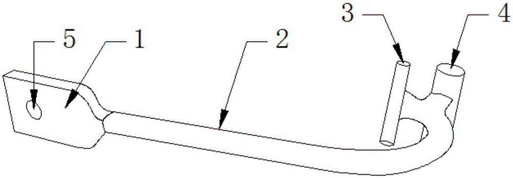
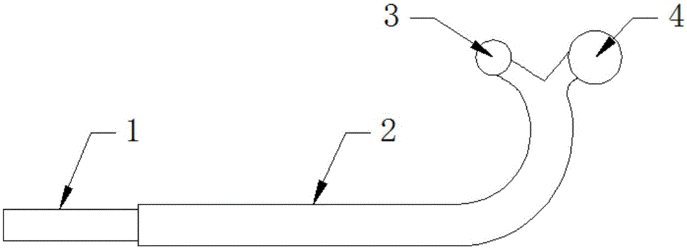
[0027] Such as figure 2 As shown, the pin puller applied to the R pin of the insulator is composed of four parts, including the handle part 1, the connecting rod 2, the first cylinder 3 and the second cylinder 4, and the first cylinder 3 and the second cylinder 4 The operating part is formed parallel to each other, the handle part 1 is connected with one end of the connecting rod 2, the other end of the connecting rod 2 is connected with the operating part, and the first cylinder 3 and the second cylinder 4 are connected with the connecting rod 2.

[0028] The hand-held part 1 is a flat structure, and the flat-plate structure is provided with a round hole 5; the round hole 5 is provided with the convenience of carrying, and can be hung on the hook of the worker's safety belt, and the hand-held part 1 is made of thicker flat iron, which can be lifted t...


PUM


Abstract

The invention discloses a pin puller applied to an insulator R pin. The pin puller comprises a handheld part, wherein the handheld part is connected with one end of a connecting rod; the other end of the connecting rod is connected with an operation part; the operation part comprises parallel first column body and second column body; the first column body and the second column body are connected with the connecting rod; and the first column body and the second column body are vertical to the other end of the connecting rod. Through arrangement of the first column body, the second column body, the connecting rod and the handheld part, a lever structure is formed; a pin is pulled by the lever principle; and the problems that original pin pulling nippers are difficult to clamp when the pin is pulled and time and energy are wasted are solved. The connecting rod of the pin puller is arranged into an arc-shaped J-type structure, the force provided to the first column body is just used for pulling the R pin outwards; and meanwhile, greater force can be provided to the first column body to pull the R pin.

Description

technical field [0001] The invention belongs to the technical field of power transmission line maintenance operations, and relates to a pin puller applied to the R pin of an insulator, in particular to a device for removing the R pin in the bowl head of an insulator. Background technique [0002] The connection part of the transmission line insulator usually uses the R pin. When removing the R pin 7 in the insulator bowl head 9, as figure 1 As shown, because the round mouth 8 of the R pin 7 is relatively small, the diameter of the jaws of the traditional pin puller 6 is larger than the diameter of the round mouth 8 of the R pin 7, so it is difficult to stretch it into the R pin 7 to clamp it , can only clamp the outside, and the outside of the R pin 7 is smooth, and it is easy to slip off after being clamped by the traditional pin puller 6; in addition, because the R pin 7 is a steel structure, after clamping the outside of the R pin 7, it must be A lot of force can be used...

Claims


Application Information

Patent Timeline
Patent Type & Authority Applications(China)
IPC IPC(8): H02G1/02
CPCH02G1/02
Inventor 宋维庭周远远宋维洋洪军李继强刘西营梁红军王成全
Owner JINING POWER SUPPLY CO OF STATE GRID SHANDONG ELECTRIC POWER CO
Why Eureka
Try Eureka