Large-scale electronic element attaching-inserting joint and attaching-inserting method therefor

An electronic component and large-scale technology, applied in the direction of electrical components, electrical components assembly printed circuit, printed circuit, etc., can solve the problem that it is difficult to ensure the insertion of large electronic components, affecting the insertion speed, insertion accuracy and work of the insertion machine. Efficiency and other issues, to achieve the effect of increasing the speed of placement and insertion, and improving the accuracy of placement and insertion

Inactive Publication Date: 2016-05-25
CENTRAL SOUTH UNIVERSITY OF FORESTRY AND TECHNOLOGY
View PDF7 Cites 6 Cited by
  • Summary
  • Abstract
  • Description
  • Claims
  • Application Information

AI Technical Summary

Problems solved by technology

[0009] The placement heads in the above patent documents are difficult to ensure that large electronic components are quickly and accurately placed on the PCB, which affects the placement speed, placement accuracy and work efficiency of the placement machine.

Method used


Image

  • Large-scale electronic element attaching-inserting joint and attaching-inserting method therefor
  • Large-scale electronic element attaching-inserting joint and attaching-inserting method therefor
  • Large-scale electronic element attaching-inserting joint and attaching-inserting method therefor

Examples


Embodiment

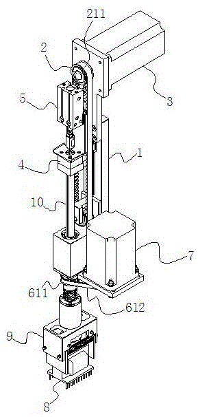
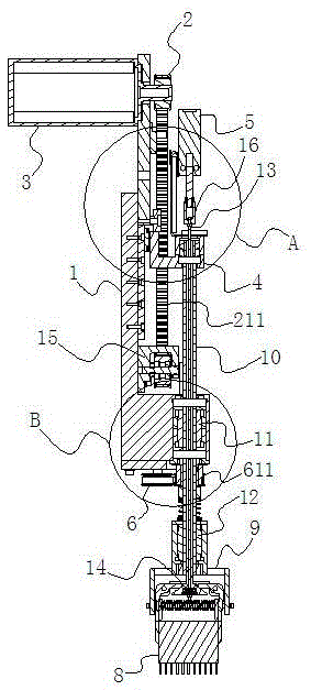
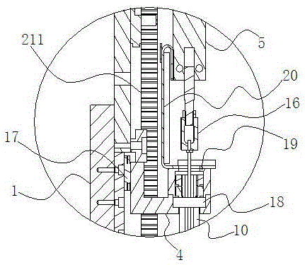
[0046] Example: such as figure 1 with figure 2 As shown, a large-scale electronic component sticking plug includes a sticking plug support 1, a synchronous belt device 2 arranged on one end of the sticking plug support 1, and a control motor 3 (synchronous belt) for driving the synchronous belt device 2 Device one 2 includes driving wheel one, driven wheel one and synchronous belt one 211), L-shaped slider 4 fixed on the synchronous belt one 211 of synchronous belt device one 2, and clamping on the L-shaped slider 4 The cylinder 5 and the timing belt device 2 6 arranged on the other end of the sticking plug support 1 and the control motor 2 7 for driving the timing belt device 2 6 (the timing belt device 2 6 includes the driving wheel 2, the driven wheel 611 and the synchronous belt Take two 612);

[0047] The large electronic component sticker plug also includes a ball spline assembly and a chuck 9 for clamping the large electronic component 8. The ball spline assembly includes...


PUM


Abstract

The invention discloses a large-scale electronic element attaching-inserting joint and an attaching-inserting method therefor. The attaching-inserting joint comprises an attaching-inserting joint supporting base, a synchronous band apparatus I, a control motor I, an L-shaped sliding block, a clamping air cylinder, a synchronous band apparatus II, a control motor II, a chuck, a spline shaft, a spline shaft sleeve I, a spline shaft sleeve II, a pull rod and a thrust bearing; under the action of the clamping air cylinder, the chuck can be controlled to be in a clamped state or in a loosened state through the chuck so as to clamp or loosen the large-scale electronic element by the chuck; by controlling the rotation of the motor I, the synchronous band apparatus I can drive the L-shaped sliding block to move up and down in a perpendicular direction so as to drive the clamping air cylinder, the pull rod, the spline shaft, the spline shaft sleeve II and the chuck to move together; a driven wheel II of the synchronous band apparatus II is fixedly connected with the outer peripheral surface of the spline shaft sleeve I; by controlling the rotation of the control motor II, the driven wheel II can be driven to rotate so as to drive the spline shaft sleeve I, the spline shaft, the spline shaft sleeve II and the chuck to rotate in a horizontal direction around the axial line of the spline shaft to realize control for the rotating angle of the chuck.

Description

Technical field [0001] The invention relates to an electronic component sticking plug and a sticking method, in particular to a large electronic component sticking plug and a sticking method. Background technique [0002] The placement machine is configured after the glue dispenser or screen printer in the production line. It is a device that accurately pastes the electronic components onto the PCB pads by moving the paste plug. The automatic placement machine is a device used to achieve high-speed and high-precision automatic placement of electronic components. It is the most critical and complex equipment in the entire SMT production. The placement machine has been developed from the early low-speed mechanical placement machine It is a high-speed optical centering placement machine, and is developing towards multi-functional, flexible connection and modularization. As a crucial functional part of the placement machine, the sticking plug can quickly and accurately stick the ele...

Claims


Application Information

Patent Timeline
Patent Type & Authority Applications(China)
IPC IPC(8): H05K3/30
CPCH05K3/303
Inventor 高自成李立君罗义阳涵疆
Owner CENTRAL SOUTH UNIVERSITY OF FORESTRY AND TECHNOLOGY
Why Eureka
Try Eureka