Adjustable shaft part drilling jig

An adjustable technology for shaft parts, applied in the direction of the drilling jig used for workpieces, etc., can solve problems such as prone to skew, unsatisfactory shape and position tolerances, single special parts, etc., to achieve reliable installation and compression, ensure the center position, good centering effect

Inactive Publication Date: 2016-06-01
GUIZHOU HANGRUI SCI & TECH
View PDF8 Cites 8 Cited by
  • Summary
  • Abstract
  • Description
  • Claims
  • Application Information

AI Technical Summary

Problems solved by technology

[0003] In the actual processing process, since there is no corresponding drilling jig to fix the shaft parts to be processed well, only a simple pressing plate or pressing block is used for compression, resulting in the processed holes are prone to skew and do not meet the shape. Bit Tolerance Requirements
Some common drilling jigs are available, but due to unreasonable structural design, they are only used for the processing of single and special parts, and cannot be used for processing holes perpendicular to the center line on both ends of shaft parts with different diameters and specifications.

Method used


Image

  • Adjustable shaft part drilling jig
  • Adjustable shaft part drilling jig
  • Adjustable shaft part drilling jig

Examples


Embodiment

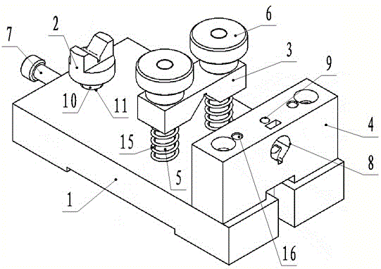
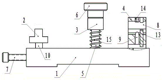
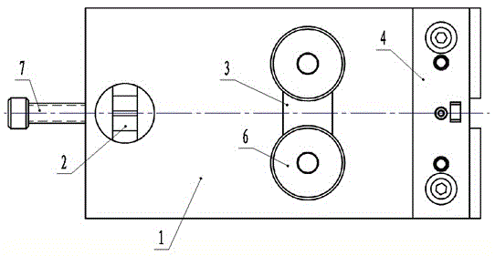
[0021] like Figure 1 to Figure 4 As shown, an adjustable shaft part drilling template includes a bottom plate 1, a floating V-shaped block 2, a compressed V-shaped block 3 and a drilling template 4, and the floating V-shaped block 2 and the drilling template 4 are respectively installed on the bottom plate 1 At the left and right ends close to each other, the floating V-shaped block 2 can float up and down and be locked by the fastening screw 7 arranged at the end of the bottom plate 1, and the pressing V-shaped block 2 is installed upside down in the middle of the base 1 On the column 5, a compression nut 6 is arranged above the compression V-shaped block 2, and the compression nut 6 is screwed on the upper end of the column 5, and a support hole 8 for supporting the workpiece to be processed is provided on the drilling template 4. The top of the drilling template 4 is provided with a drilling template hole 9 that runs through the support hole 8 downwards, and a drill sleeve...


PUM


Abstract

The invention discloses an adjustable shaft part drilling jig which comprises a base plate (1), a floating V-shaped block (2), a pressing V-shaped block (3) and a drilling jig plate (4), wherein the floating V-shaped block (2) and the drilling jig plate (4) are mounted close to left and right ends on the base plate (1), respectively; the floating V-shaped block (2) is capable of floating up and down and is locked by a fastening bolt (7) arranged on the end part of the base plate (1); a drilling jig hole (9) downward penetrating through a supporting hole (8) is formed in the top of the drilling jig plate (4); a drilling sleeve (14) is arranged at the opening of the drilling jig hole (9). The adjustable shaft part drilling jig is fit for clamping to-be-processed shafts in different diameters by adjusting the height of the floating V-shaped block; the axial lines of the to-be-processed shafts are kept horizontal; the floating V-shaped block and the pressing V-shaped block are used for supporting and pressing the processed shaft parts, so that the processed shaft parts are reliably mounted and pressed; the adjustable shaft part drilling jig has an excellent centering function and can guarantee the central positions of the shafts.

Description

technical field [0001] The invention relates to an adjustable shaft part drilling mold, which belongs to the technical field of mechanical processing auxiliary equipment. Background technique [0002] The holes perpendicular to the center line on both ends of the shaft parts are processed. In addition to the size requirements of the hole, the shape and position tolerance requires that the center of the hole and the center of the shaft have perpendicularity and symmetry requirements. [0003] In the actual processing process, since there is no corresponding drilling jig to fix the shaft parts to be processed well, only a simple pressing plate or pressing block is used for compression, resulting in the processed holes are prone to skew and do not meet the shape. bit tolerance requirements. Existing common jigs, but due to unreasonable structural design, are only used for the processing of single, special parts, and cannot be applied to the holes perpendicular to the center li...

Claims


Application Information

Patent Timeline
Patent Type & Authority Applications(China)
IPC IPC(8): B23B47/28
CPCB23B47/28B23B2247/12
Inventor 葛贤王欢石健张玉华冉文芳
Owner GUIZHOU HANGRUI SCI & TECH
Why Eureka
Try Eureka