Method for detecting abrasion difference of cutter teeth of high-speed milling cutters under action of vibration

A detection method and high-speed milling technology, applied in measuring/indicating equipment, metal processing mechanical parts, metal processing, etc., can solve the problem of not being able to achieve coordinated control of multiple cutter tooth wear, and not revealing the specific impact mechanism of vibration on the contact relationship between cutters and workers. , lack of safety prototype tools and other issues

Active Publication Date: 2016-06-01
HARBIN UNIV OF SCI & TECH
View PDF6 Cites 15 Cited by
  • Summary
  • Abstract
  • Description
  • Claims
  • Application Information

AI Technical Summary

Problems solved by technology

This method achieves the purpose of suppressing the wear of the cutter tooth at the cost of reducing the production efficiency by reducing the cutting parameters, and only solves the wear problem of a single cutter tooth, without considering the wear difference of multiple cutter teeth, and cannot achieve multi-cutter wear. Coordinated control of the wear of individual cutter teeth cannot ...

Method used


Image

  • Method for detecting abrasion difference of cutter teeth of high-speed milling cutters under action of vibration
  • Method for detecting abrasion difference of cutter teeth of high-speed milling cutters under action of vibration
  • Method for detecting abrasion difference of cutter teeth of high-speed milling cutters under action of vibration

Examples


Embodiment Construction

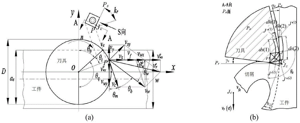
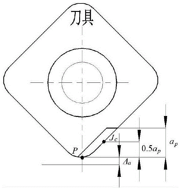
[0100] 1. Establish the relationship between the cutting speed of the high-speed milling cutter and the contact between the cutter and the cutter under the action of vibration, such as figure 1 At the same time, select the maximum position of the wear width on the cutting edge, that is, the middle section of the cutting edge as the base point J c ,like figure 2 shown.

[0101] figure 1 medium, v f is the feed speed of the cutter teeth (m / s), v c is the cutting speed of the cutter teeth (m / s), v w is the cutting speed v in the feed plane c with the feed rate v f The composite speed (m / s), v wx is v of the feed plane w The velocity component in the x-direction (m / s), v wy is v of the feed plane w Velocity component in the y direction (m / s), v x is the velocity component of the vibration velocity in the x direction (m / s), v y is the velocity component of the vibration velocity in the y direction (m / s), v z is the velocity component (m / s) of the vibration velocity in...


PUM


Abstract

The invention discloses a method for detecting the abrasion difference of cutter teeth of high-speed milling cutters under the action of vibration. The method is technically characterized by comprising the steps that firstly, the cutter tooth cutting motion speed and cutter skill contact relation under the action of vibration is built; secondly, a rear angle calculating equation under the action of vibration is calculated; thirdly, a cutter tooth friction contact point position calculating model and a cutter tooth friction contact point friction speed calculating model are constructed; fourthly, cutter tooth friction contact point positions and the cutter tooth friction contact point friction speed are analyzed, and the change rules of the cutter tooth friction contact point positions and the cutter tooth friction contact point friction speed are obtained; fifthly, an abrasion cutting test of the high-speed milling cutters is carried out; sixthly, cutting vibration signals are extracted and processed; seventhly, milling cutter abrasion cutting test data obtained in the fifth step is extracted; eighthly, the test results of the cutter tooth rear cutter face friction contact point positions and the friction contact point friction speed are obtained; and ninthly, a cutter tooth rear cutter face friction contact state model is verified. According to the method, bases are provided for relieving uneven abrasion and weakening fluctuating load excitation, and initial sample cutters are provided for efficient and high-precision cutting.

Description

Technical field: [0001] The invention relates to a method for detecting wear of a high-speed milling cutter, in particular to a method for detecting the difference of tooth wear of a high-speed milling cutter under the action of vibration. Background technique: [0002] In the process of high-speed milling, the initial wear difference of forced vibration under the impact of intermittent load affects the force state of the tool. In actual machining, problems such as severe tool wear, obvious tool vibration, low quality of the machined surface, serious tool damage, and reduced tool efficiency and service life are common, which seriously increases the uncertainty of milling cutter failure, and restricts it. The safety of milling cutters and the application of efficient milling in the machining of important parts and other fields. [0003] Different from ordinary milling, the cutting parameters used in high-efficiency milling are generally relatively large, and the consequence ...

Claims


Application Information

Patent Timeline
IPC IPC(8): B23Q17/09
CPCB23Q17/0957B23Q2717/006
Inventor 姜彬张明慧姚贵生
Owner HARBIN UNIV OF SCI & TECH
Why Eureka
Try Eureka