Hanging sling for unmanned underwater vehicle water surface launching and retrieving
A technology of unmanned aerial vehicle and spreader, which is applied in the direction of load hanging components, ships, and ship salvage, etc., can solve problems such as hidden safety hazards of staff, and achieve the effect of efficient lifting work, convenient operation, and reliable docking.
- Summary
- Abstract
- Description
- Claims
- Application Information
AI Technical Summary
Problems solved by technology
Method used
Image

Examples
specific Embodiment approach 1
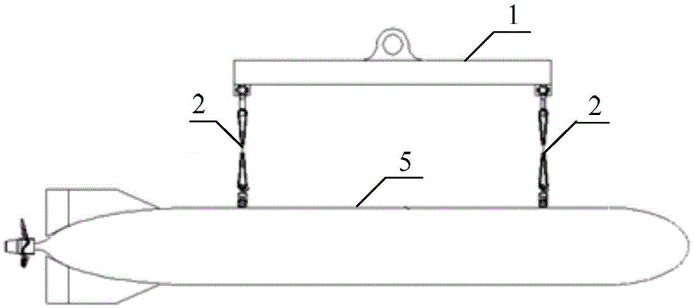
[0018] Specific implementation mode one: combine figure 1 Describe this embodiment, the hoisting sling for the deployment and recovery of underwater unmanned vehicles described in this embodiment includes a balance boom 1, two slings 2, two hoisting sockets 3 and two hoisting plug 4;
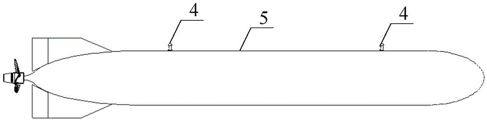
[0019] The middle position of the balance suspension bar 1 is provided with a mounting hole, and one end of the two suspenders 2 is respectively fixed on the two ends of the balance suspender 1, and the other ends of the two suspenders 2 are respectively fixed on two lifting sockets 3, two The lifting plug 4 is respectively fixed on the two ends of the underwater unmanned vehicle;
[0020] The lifting plug 4 includes a plug rod and a plug cap, and the plug cap is fixed on one end of the plug rod;
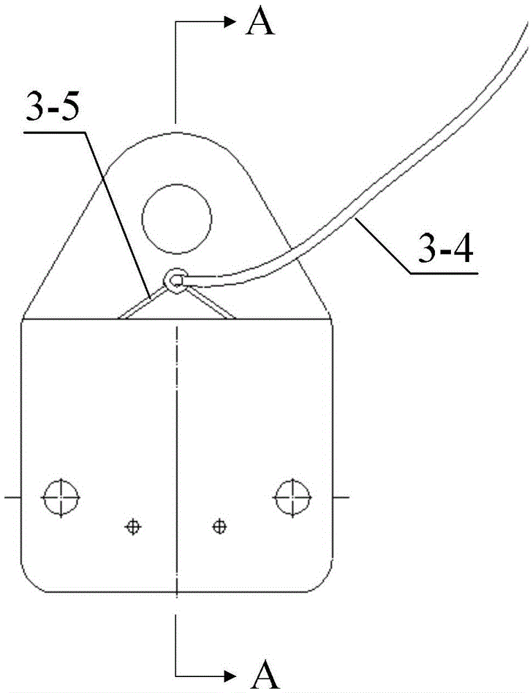
[0021] The lifting socket 3 includes a socket body provided with a socket hole 3-1, a control wire 3-4 and two fixed wires 3-5, and two opposite hook heads are embedded inside the side wall of the s...
specific Embodiment approach 2
[0031] Specific implementation mode two: combination Figure 6 Describe this embodiment. This embodiment is a further limitation of the lifting sling for underwater unmanned vehicle surface deployment and recovery described in Embodiment 1. In this embodiment, inside the socket hole 3-1 And near the intersection of the bottom surface of the socket hole 3-1 and the side wall, two rotating shafts 3-6 are arranged, and the two rotating shafts 3-6 are used to support the two fixed wires 3-5.
[0032] Such as Figure 6 As shown, the rotating shaft 3-6 is located at the position where the bottom surface of the socket hole 3-1 intersects with the side wall. When the control line 3-4 is pulled, the force direction of the two fixed lines 3-5 and the fixed points of the hook mechanism 3-2 Close to the vertical direction, the effective rotation of the hook mechanism 3-2 can be realized with a small control force.
PUM
 Abstract
Description
Claims
Application Information
 - R&D Engineer
- R&D Manager
- IP Professional
- Industry Leading Data Capabilities
- Powerful AI technology
- Patent DNA Extraction
Browse by: Latest US Patents, China's latest patents, Technical Efficacy Thesaurus, Application Domain, Technology Topic.
© 2024 PatSnap. All rights reserved.Legal|Privacy policy|Modern Slavery Act Transparency Statement|Sitemap