Cable sheath-core separation equipment for new energy equipment recovery

A technology for new energy equipment and separation equipment, which is applied in recycling technology, electronic waste recycling, circuits, etc., and can solve the problems of cable fixation and difficult cutting.

Pending Publication Date: 2021-12-31
深圳市微点流体技术有限公司
View PDF0 Cites 0 Cited by
  • Summary
  • Abstract
  • Description
  • Claims
  • Application Information

AI Technical Summary

Problems solved by technology

[0004] In order to overcome the disadvantage that it is difficult for people to fix and cut the cables in the existing cutting methods, the technical problem of the present invention is: to provide a new energy equipment recovery device that can fix the cables and has a better cutting effect. Cable skin-core separation equipment

Method used


Image

  • Cable sheath-core separation equipment for new energy equipment recovery
  • Cable sheath-core separation equipment for new energy equipment recovery
  • Cable sheath-core separation equipment for new energy equipment recovery

Examples


Embodiment 1

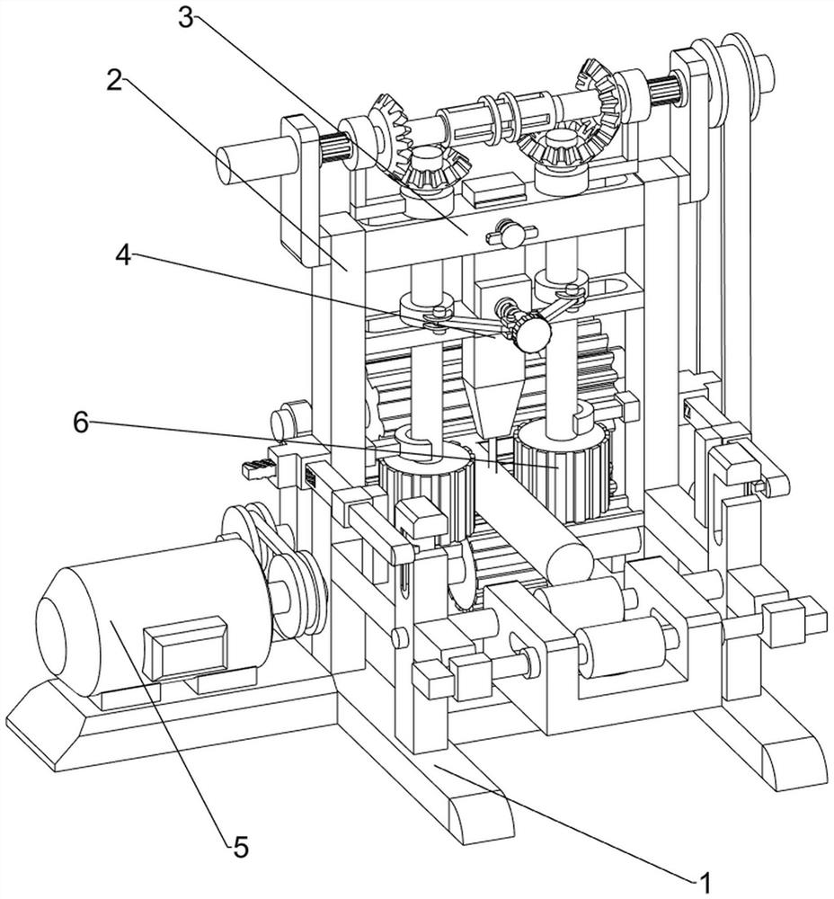
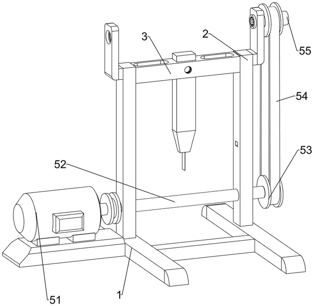
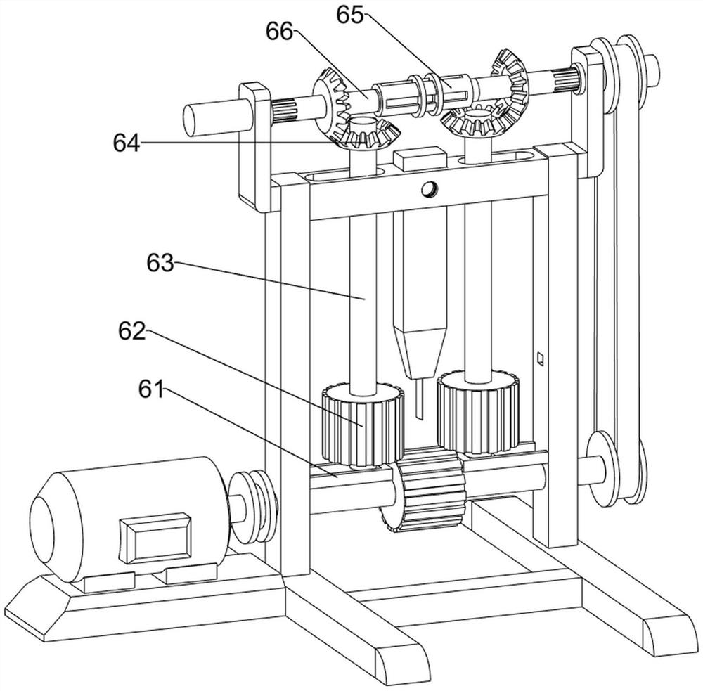
[0030] A cable skin-core separation device for recycling new energy equipment, such as figure 1 , figure 2 and image 3 As shown, it includes a base 1, a first bracket 2, a first fixed frame 3, a cutting knife 4, a driving mechanism 5 and a fixed delivery mechanism 6, and the rear side of the top of the base 1 is symmetrically provided with a first bracket 2, and the first bracket 2 The first fixed frame 3 is arranged between the upper parts, the middle part of the first fixed frame 3 is slidingly provided with a cutting knife 4, the top of the base 1 is provided with a driving mechanism 5, and a fixed conveyor is provided between the first bracket 2 and the first fixed frame 3. Institution 6.

[0031] When people need to use this equipment, first insert the head end of the cable between the fixed conveying mechanism 6, fix the cutting knife 4 according to the size of the cable, and then start the driving mechanism 5, so that the driving mechanism 5 drives the fixed conveyi...

Embodiment 2

[0036] On the basis of Example 1, such as Figure 4 , Figure 5 , Figure 6 , Figure 7 , Figure 8 and Figure 9 As shown, it also includes a second fixed mount 7, a splint 8, a first thumb screw 9, a guide rod 10, a first fixed block 11, a connecting rod 12, a nut 13 and a second thumb screw 14, and the second rotating sleeve 66 is equipped with a second fixed mount 7 in a sliding manner, and the second fixed mount 7 is connected with the first rotating rod 63 and the bevel gear 64. The front side of the first fixed mount 3 is threaded with the first hand screw 9 , the rear side rotation of the first hand screw 9 is provided with a splint 8, the splint 8 cooperates with the cutting knife 4, and the inner side of the first support 2 top is provided with a guide rod 10, and the first rotation rod 63 is positioned on the guide rod 10. Sliding up, the first rotating rod 63 is provided with the first fixed block 11, the front side of the first fixed block 11 is provided with...


PUM


Abstract

The invention relates to cable sheath-core separation equipment, in particular to cable sheath-core separation equipment for new energy equipment recovery. The invention provides the cable sheath-core separation equipment for new energy equipment recovery, which can fix a cable and has a relatively good cutting effect. The cable sheath-core separation device for new energy equipment recovery comprises a base, wherein first supports are symmetrically arranged at the top of the base; a first fixing frame arranged between the upper parts of the first supports; a cutting knife arranged in the middle of the first fixing frame in a sliding mode; a driving mechanism arranged at the top of the base; and a fixed conveying mechanism is arranged between the first supports and the first fixing frame. According to the invention, the driving mechanism and the fixed conveying mechanism are arranged, so that the cable automatically moves forwards, and then the cable is cut under the cooperation of the cutting knife.

Description

technical field [0001] The invention relates to a cable skin-core separation device, in particular to a cable skin-core separation device for recycling new energy equipment. Background technique [0002] After the cable is discarded, people usually collect the cable, and then cut the cable to separate the outer sheath and the inner core of the cable. Usually, people cut the cable directly with a blade, but the cable is It is easy to shift when being cut, so people need to fix the cable, and because the outer skin of the cable is relatively smooth, it is not easy for people to cut. [0003] Therefore, in view of the above shortcomings, we need to develop a new energy equipment recovery cable skin-core separation device that can fix the cable and has a better cutting effect. Contents of the invention [0004] In order to overcome the disadvantage that the existing cutting method requires people to fix and cut the cables which are relatively difficult, the technical problem ...

Claims


Application Information

Patent Timeline
Patent Type & Authority Applications(China)
IPC IPC(8): H01B15/00
CPCH01B15/005Y02W30/82
Inventor 张春燕
Owner 深圳市微点流体技术有限公司
Why Eureka
Try Eureka