Washing machine inner barrel

A washing machine and inner tub technology, applied in the field of washing machines, can solve problems such as affecting the washing effect of clothes and cross-infection of laundry, and achieve the effects of eliminating the possibility of water leakage, avoiding cross-infection, and saving washing water.

Pending Publication Date: 2016-06-01
QINGDAO HAIER WASHING MASCH CO LTD
View PDF2 Cites 13 Cited by
  • Summary
  • Abstract
  • Description
  • Claims
  • Application Information

AI Technical Summary

Problems solved by technology

These molds are caused by a large amount of dirt accumulated inside the washing machine that has been used for a long time and cannot be effectively removed to breed and reproduce. If the dirt that is invisible to the user is not removed, the bacteria will adhere to the clothes again after the next wash. Brought to the human b...

Method used


Image

  • Washing machine inner barrel
  • Washing machine inner barrel
  • Washing machine inner barrel

Examples


Embodiment 1

[0044] The bucket body and the bottom of the inner bucket described in this embodiment have an integral injection molding structure (not shown in the figure).

Embodiment 2

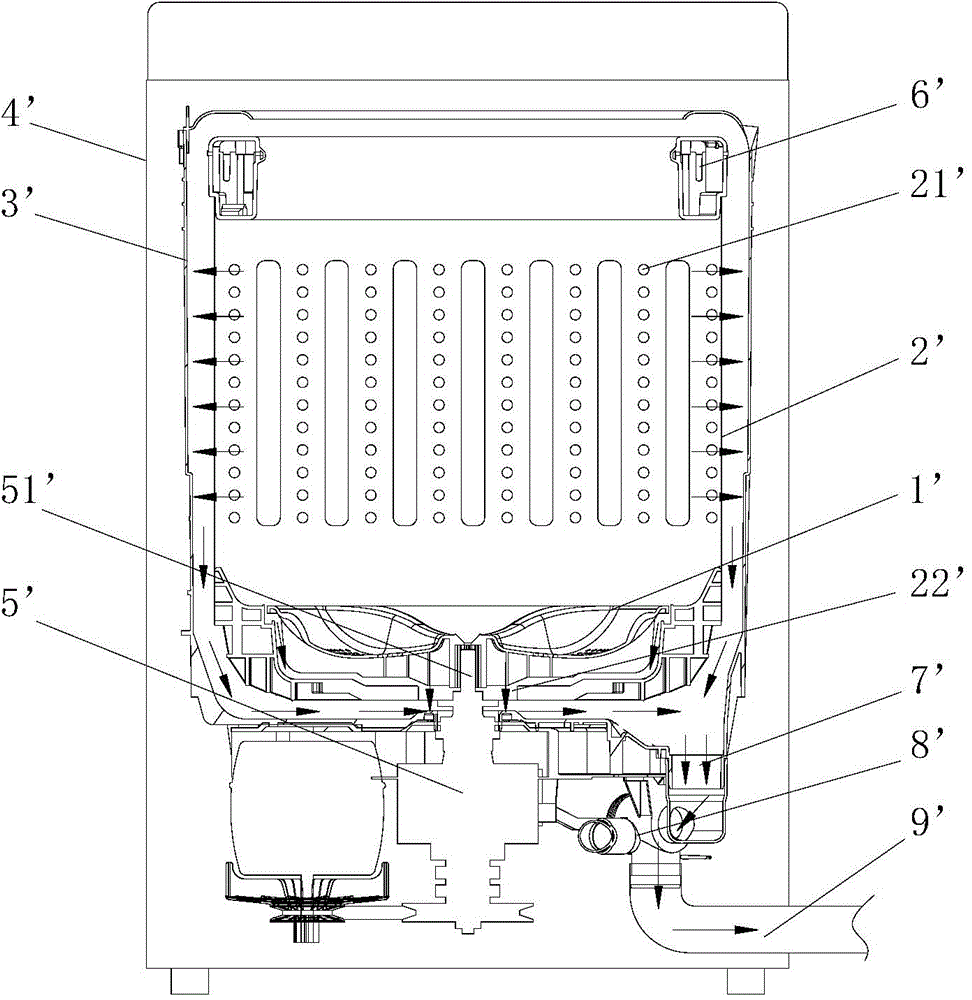
[0046] Such as Figure 5 and Figure 6 As shown, the bucket body 2 described in this embodiment is provided with a circle of pressure profile 21 along the circumference, and the pressure profile 21 cooperates with the upper end surface of the inner barrel bottom peripheral wall 31 to form a blocking support structure, and a sealing ring 6 is arranged between the two to form Face seal.

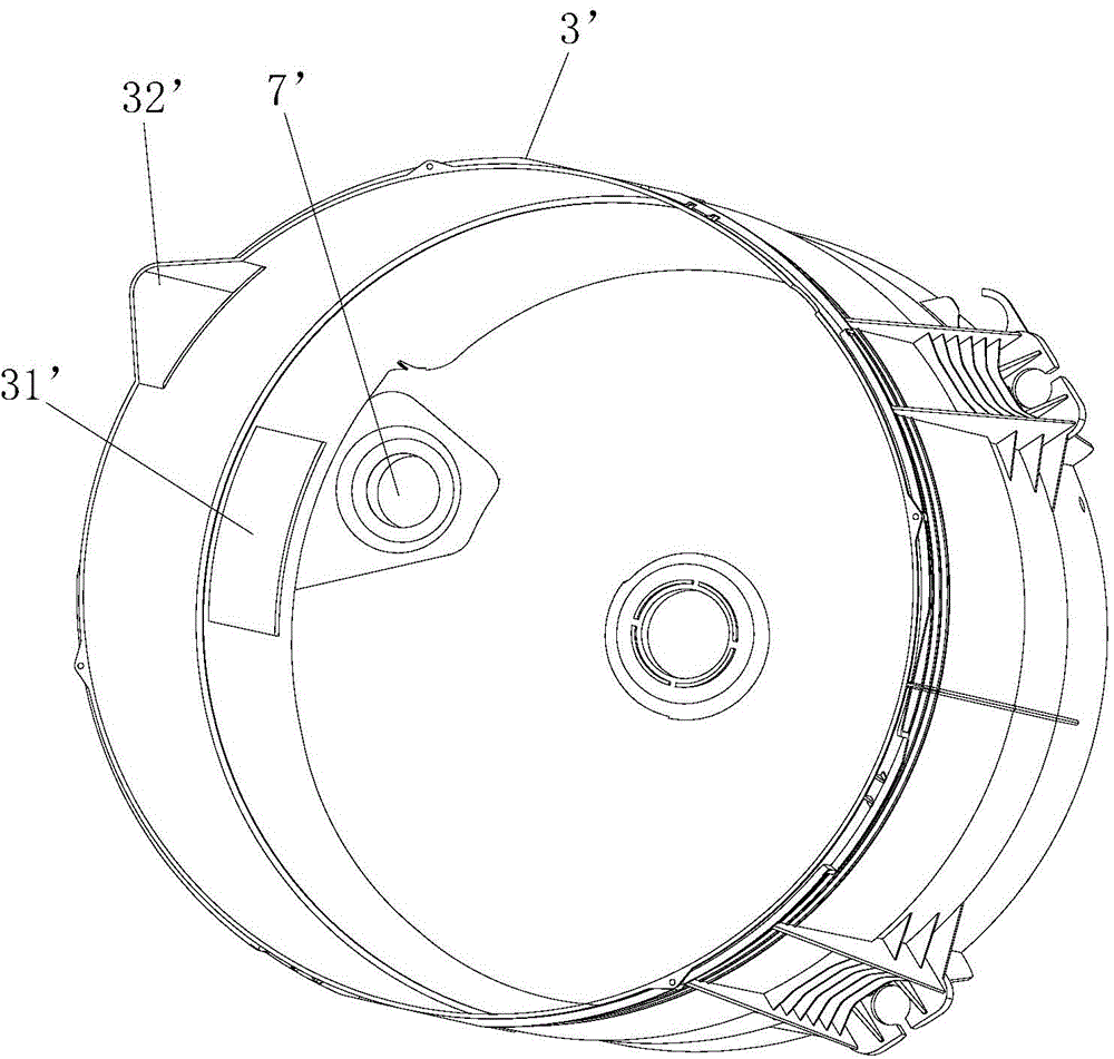
[0047] Further, the barrel body profile 21 is stamped from outside to inside, forming a circle of protruding barrier ribs 22 on the inner wall of the barrel body 2, and a flange 32 is provided radially outward on the inner barrel bottom peripheral wall 31, The flange 32 is supported under the barrier rib 22 formed by profiling, and the sealing ring 6 is sandwiched between them.

[0048] Preferably, the contact surface formed between the barrier rib 22 and the flange 32 forms a horizontal plane structure or a downwardly inclined plane structure outward from the center, and this structure facil...

Embodiment 3

[0050] Such as Figure 6 and Figure 7 As shown, the present embodiment is a further improvement on the basis of the second embodiment: the upper surface of the flange 32 is provided with an annular groove 33, and the sealing ring 6 is positioned through the annular groove 33, and the lower surface of the barrier rib 22 and the protrusion The upper surface of the edge 32 presses the sealing ring 6 to form an end face seal. This structure further prevents the sealing ring from falling off and has a longer service life.

[0051] Preferably, the sealing ring 6 is an annular flat body structure, the lower surface is provided with an annular rib 61, and the annular rib 61 is correspondingly installed in the annular groove 33 provided on the upper surface of the flange 32 (see Figure 7 ).


PUM


Abstract

The invention discloses a washing machine inner barrel. The washing machine inner barrel comprises a barrel body, an inner barrel bottom arranged on the lower part of the barrel body, and a balancing ring arranged on the upper opening of the barrel body. The upper part of the inner barrel is provided with a water outlet, a water holding structure is arranged under the water outlet, and the barrel body is in seal connection with the inner barrel bottom. Specifically, the barrel body and the inner barrel bottom form an integral injection moulding structure; or the barrel body is provided with a loop of profiled part along the circumference, the profiled part is matched with the upper end face of the circumferential wall of the inner barrel bottom to form a blocking and supporting structure, a sealing ring is arranged between the profiled part and the inner barrel bottom, and end face seal is formed; or a sealing ring or a seal cartridge is arranged between the circumferential wall of the inner barrel bottom and the lower part of the barrel body, the inner wall of the seal cartridge is provided with at least two loops of convex ribs, and each loop of convex rib is correspondingly arranged in a mounting groove which is arranged in the external surface of the circumferential wall of the inner barrel bottom in the circumferential direction; or the lower part of the barrel body sleeves the outer surface of the circumferential wall of the inner barrel bottom, the lower edge of the barrel body is bent inwards to form a bound edge, the bound edge is connected with the inner barrel bottom, and the bound edge is inside provided with a sealing ring. The washing machine inner barrel is simple in structure and good in sealing effect, and can be installed conveniently, stably and firmly.

Description

technical field [0001] The invention relates to the field of washing machines, in particular to an inner tub of a washing machine. Background technique [0002] Existing pulsator washing machines, such as figure 1 As shown, it generally includes a pulsator 1', an inner barrel 2', an outer barrel 3' and a box body 4' arranged in sequence from the inside to the outside, wherein the pulsator 1' is arranged at the bottom center of the inner barrel 2' and can be driven by a driving device 5 ' Drive the rotation. The top of the inner tub 2' is provided with a balance ring 6', and the side wall of the inner tub 2' is longitudinally provided with multiple rows of dewatering holes 21', and the bottom of the inner tub 2' is provided with a drain hole 22', which is also The output shaft 51' of the driving device 5' is passed through. Such as figure 2 As shown, an air chamber 31' and a water level sensor (not shown in the figure) are provided at the bottom of the side wall of the o...

Claims


Application Information

Patent Timeline
IPC IPC(8): D06F37/12D06F39/10
Inventor 吕佩师张刚金田云程宝珍
Owner QINGDAO HAIER WASHING MASCH CO LTD
Why Eureka
Try Eureka