

Method for mounting pile-stabilizing positioning platform
A positioning platform and pile stabilizing technology, which is applied in the field of engineering pile stabilizing, can solve the problems of difficult to grasp the accuracy, cumbersome, complicated operation, etc., and achieve the effect of high accuracy, high positioning precision and simple operation
- Summary
- Abstract
- Description
- Claims
- Application Information
AI Technical Summary
Problems solved by technology
Method used
Image

Examples
Embodiment 1
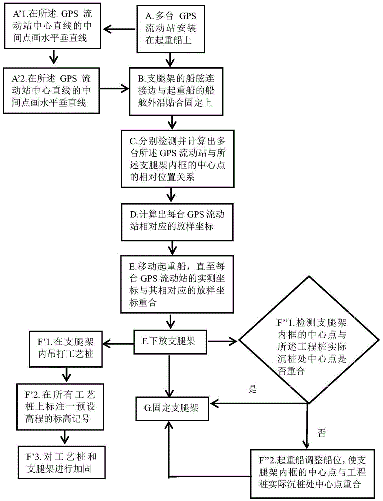
[0037] A method for installing a stable pile positioning platform, A. multiple GPS mobile stations 5 are installed on the crane ship 6;
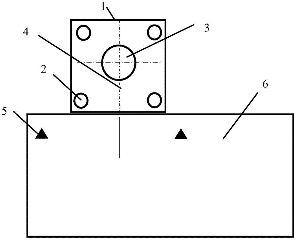
[0038] B. The shipboard connecting edge of the outrigger frame 1 and the shipboard outer edge of the crane ship 6 are attached and fixed, and the outrigger frame 1 is used to build a stable pile positioning platform, and the inner frame of the outrigger frame 1 and the engineering pile 3 to adapt to the outer diameter;
[0039] C respectively detects and calculates the relative positional relationship between a plurality of GPS rover stations 5 and the central point of the inner frame of the outrigger frame;
[0040] D. With reference to the relative positional relationship between a plurality of GPS mobile stations 5 and the center point of the inner frame of the outrigger frame, the coordinates corresponding to each GPS mobile station 5 are calculated by the coordinates of the center point of the actual pile sinking place of the engineerin...
Embodiment 2
[0048] On the basis of embodiment one, described embodiment two has been further improved, and described GPS mobile station 5 is provided with two, and the straight line that the center of two described GPS mobile stations 5 connects gained and described crane ship 6 The outer edge of the side of the ship is parallel, and the distance between the two GPS rover stations 5 is greater than the width of the pile platform. The side length distance between large GPS rover stations is conducive to improving the positioning accuracy of the outrigger center and reducing errors.
[0049] As long as the relative position relationship between the two GPS rover stations 5 and the center point of the inner frame of the outrigger frame is detected and calculated, the stakeout coordinates of the two GPS rover stations 5 can be calculated.
[0050] When the central line of the GPS mobile station is parallel to the shipboard of the lifting ship 6, when detecting the angle between any point (suc...
Embodiment 3
[0052] On the basis of embodiment two, described embodiment three has been further improved, after described step A, carry out step A':
[0053] A'1. Draw a horizontal line 4 perpendicular to the GPS rover center straight line at the middle point of the GPS rover center straight line;
[0054] A'2. Lift and move the outrigger frame 1, and when the center point of the inner frame of the outrigger frame is on the horizontal line 4, perform step B.
[0055] Execution of the step A' is for the purpose of detecting and calculating the relative positional relationship between the two GPS rover stations 5 and the center point of the inner frame of the outrigger frame more conveniently in the step C. The center point of the inner frame of the outrigger frame is located on the horizontal line 4, that is to say, the distance from the center point of the inner frame of the outrigger frame to the two GPS mobile stations 5 is equal, and the inner frame of the outrigger frame The central p...
PUM
 Abstract
Description
Claims
Application Information