
Fuel Flow Restriction Valves for Large Internal Combustion Engines

A large-scale internal combustion engine, fuel flow technology, applied in the direction of fuel injection device, charging system, mechanical equipment, etc., can solve problems such as valve seat sealing discount

Active Publication Date: 2018-12-14
OMT OFF MEC TORINO
View PDF7 Cites 0 Cited by
  • Summary
  • Abstract
  • Description
  • Claims
  • Application Information

AI Technical Summary

Problems solved by technology

Without these processing operations, the sealing performance of the valve seat will be greatly reduced.

Method used


Image

  • Fuel Flow Restriction Valves for Large Internal Combustion Engines
  • Fuel Flow Restriction Valves for Large Internal Combustion Engines

Examples


Embodiment Construction

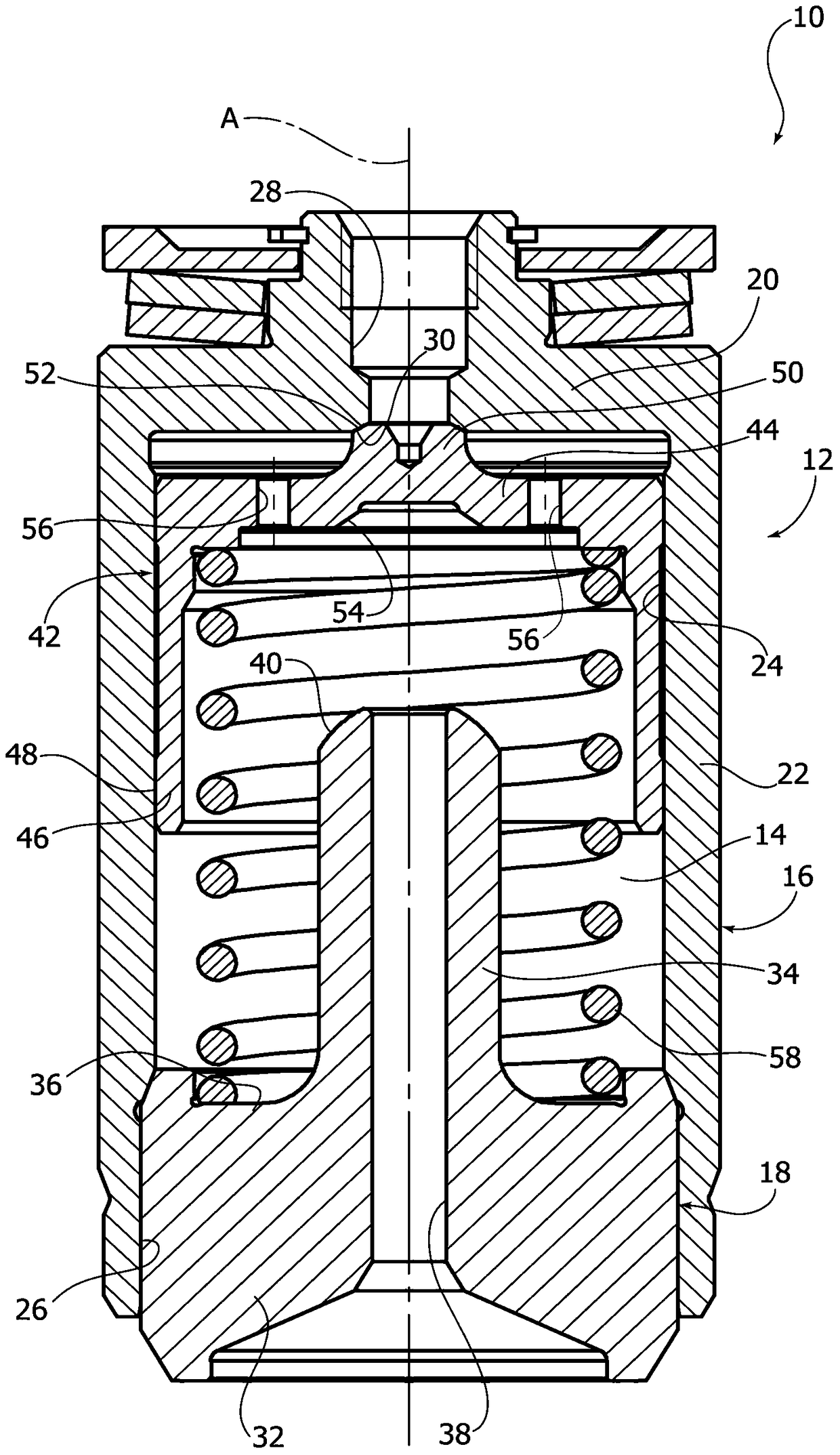
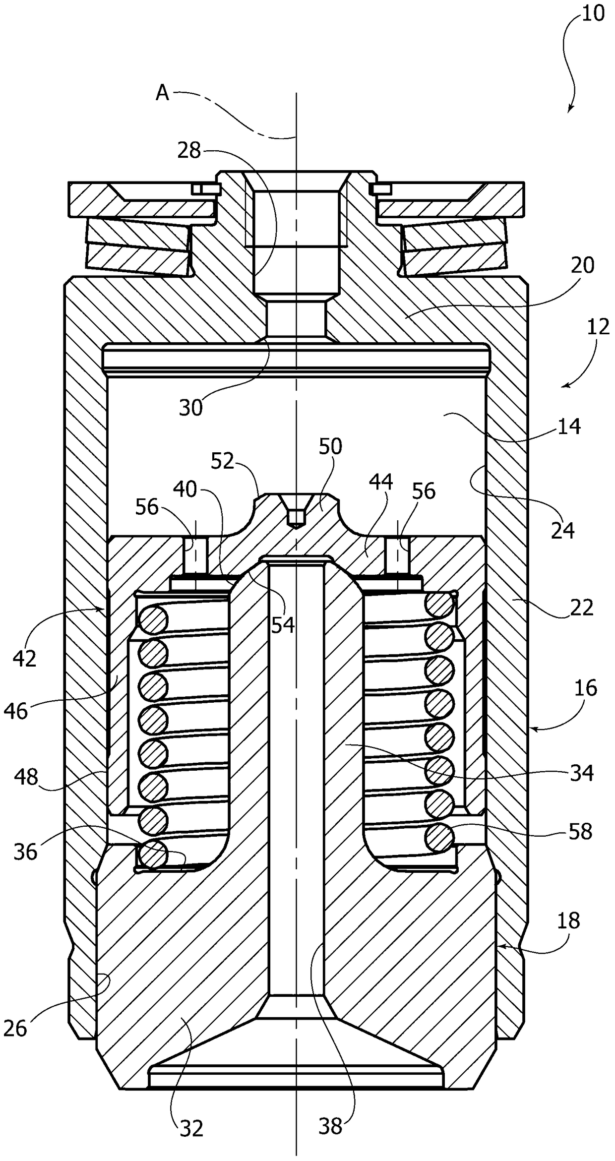
[0026] Referring to the drawings, reference numeral 10 denotes a fuel flow restriction valve intended to be used in a common rail injection system for a large internal combustion engine. The fuel flow restriction valve 10 includes a valve housing 12 defining a valve cavity 14 therein. The valve housing 12 is formed by a first housing 16 and a second housing 18 fixed to each other.

[0027] The first housing 16 includes a bottom wall 20 , and a side wall 22 extending from the bottom wall 20 and having a cylindrical inner surface 24 surrounding the valve cavity 14 . The side wall 22 of the first housing 16 has an open end portion 26 into which the second housing 18 is inserted and secured. An inlet passage 28 is formed on the bottom wall 20 of the first housing 16 , which communicates with the valve cavity 14 . The inboard end of the inlet passage 28 has an inlet valve seat 30 . In the example described, the inlet valve seat is formed by a conical concave surface.

[0028] T...


PUM


Abstract

A fuel flow limiting valve for large internal combustion engines, comprising: - a valve housing (12) including an inner cylindrical surface (24) surrounding a valve chamber (14), an inlet channel (28) with an inlet valve seat (30), an outlet channel (38) with an outlet valve seat (40), - a valve piston (42) housed in said valve chamber (14) and having a base wall (44) and a cylindrical wall (46), which is guided in a longitudinal direction (A) from said inner cylindrical surface (24) of the valve housing (12), the valve piston (42) having a first sealing surface (52) cooperating with the inlet valve seat (30) and a second sealing surface (54) cooperating with the outlet valve seat (40), the valve piston (42) being movable in said longitudinal direction (A) between a first position in which the first sealing surface (52) closes the inlet valve seat (30) and a second position in which the second sealing surface (54) closes the outlet valve seat (40), and - an elastic element (58) arranged between the housing (12) and the valve piston (42) and tending to push the valve piston (42) towards said first position, wherein the first and the second sealing surfaces (52, 54) are machined directly onto said base wall (44) of the valve piston (42) and wherein the valve housing (12) comprises a pin formation (34), which extends in the longitudinal direction within said valve chamber (14).

Description

technical field [0001] The present invention relates to a fuel flow restriction valve for large internal combustion engines. [0002] The valve according to the invention is especially useful for large marine engines with common rail injection systems. Background technique [0003] Because the common rail injection system can select the injection pressure and injection timing regardless of the engine speed and fuel cam design, it produces greater flexibility in the control of the internal combustion engine, and in the control of injection flow through multi-point injection There is greater flexibility in adjustments. [0004] This is all achieved by assigning the pressure generator and injection control functions to the individual components previously assigned to the fuel injection pump (high pressure pump and electronically controlled injector, respectively). [0005] In this type of injection system, the injector is always connected to the high-pressure fuel accumulator...

Claims


Application Information

Patent Timeline
Patent Type & Authority Patents(China)
IPC IPC(8): F02M63/02
CPCF02M63/0215F02M55/02F02M63/0033F02M63/0054F02M63/0075F02M63/0225
Inventor 卡洛·科西多
Owner OMT OFF MEC TORINO
Learn More