Spiral centrifugal fan and air treatment device

A centrifugal fan and spiral technology, applied in mechanical equipment, non-displacement pumps, non-variable volume pumps, etc., can solve the problems of low air pressure, large air volume, and large volume, and achieve high air pressure, large air volume, and volume small effect

Inactive Publication Date: 2016-06-01
柴俊麟
View PDF5 Cites 9 Cited by
  • Summary
  • Abstract
  • Description
  • Claims
  • Application Information

AI Technical Summary

Problems solved by technology

The structure of the axial flow fan is simple, the air volume is large but the wind pressure is low, and the wind direction of the inlet and outlet is axial, so it is difficult to apply to the design of air purifiers that require high wind pressure; the wind pressure of the centrifugal fan is hig

Method used


Image

  • Spiral centrifugal fan and air treatment device
  • Spiral centrifugal fan and air treatment device
  • Spiral centrifugal fan and air treatment device

Examples


Embodiment 1

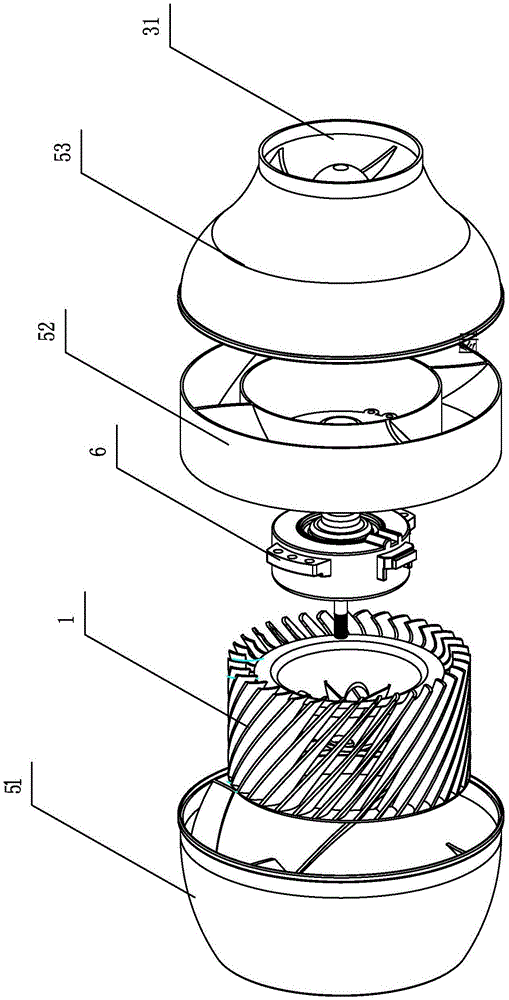
[0030] Embodiment 1, with reference to attached figure 1 , 2 , 3, 3a, 4, 4a, 5a, 5b, 5c, 8.

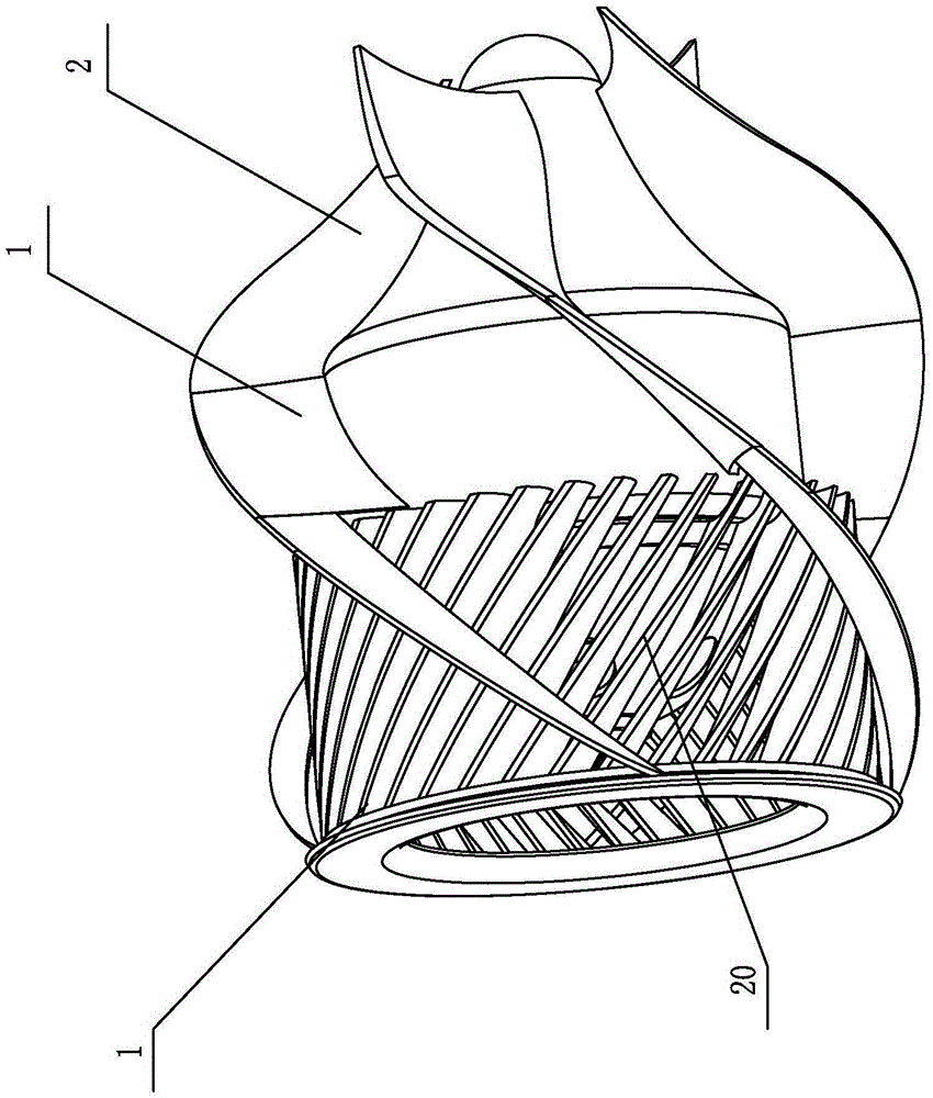
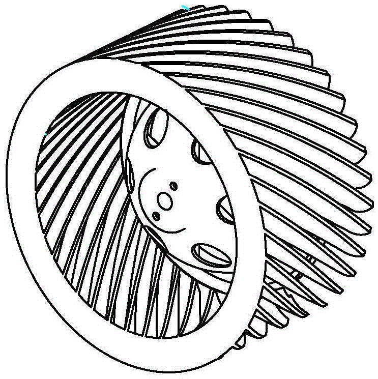
[0031] The spiral centrifugal fan provided by the present invention includes a motor 6 , a centrifugal rotor 1 and a centrifugal rotor housing 3 , and the motor 6 drives the centrifugal rotor 1 to rotate. The centrifugal wind wheel 1 is located at the center of the centrifugal wind wheel shell; the inner wall of the centrifugal wind wheel shell is provided with more than one spiral air duct (for example, 5 in this embodiment), and the spiral air duct is in the On the periphery of the centrifugal wind wheel 1, its air inlet 20 is located on the radially outer side of the centrifugal wind wheel 1. The blades 10 of the centrifugal wind wheel are inclined to the rotation axis of the centrifugal wind wheel, and the wind discharged by the wind blades 10 can smoothly enter the spiral The air channel 2 avoids hitting the wall of the air channel as much as possible. The spiral air channel gu...

Embodiment 2

[0039] Embodiment 2, with reference to attached Figure 6 , 7 ,8.

[0040] In this embodiment, the snail shape is an involute snail shape, and reference numeral 53b is the front end section of the casing of the centrifugal fan. Other parts of this embodiment are the same as Embodiment 1, in Figure 6 , 7 , 8 reference numbers and figure 1 , 2 , 3, 3a, 4, 4a, 5a, 5b, and 5c represent the same meaning.


PUM


Abstract

The invention provides a spiral centrifugal fan. A centrifugal wind wheel of the centrifugal fan is located at the center position of a centrifugal wind wheel shell. One or more spiral air flues are arranged on the inner wall of the centrifugal wind wheel shell. The spiral air flues are located on the periphery of the centrifugal wind wheel, and air inlets of the spiral air flues are located in the radial outer side of the centrifugal wind wheel. Blades of the centrifugal wind wheel incline relative to the rotating axis of the centrifugal wind wheel. Air exhausted by the centrifugal wind wheel is forwards guided spirally through the spiral air flues. The spiral centrifugal fan has the beneficial effects of an axial flow fan and the beneficial effects of a centrifugal fan, axial air discharging can be achieved, and the beneficial effect of the high wind pressure of the centrifugal fan is achieved as well. Meanwhile, the noise of the spiral centrifugal fan is lower than that of the centrifugal fan, the size of the spiral centrifugal fan is smaller than that of the centrifugal fan, and the spiral centrifugal fan is noiseless, high in wind pressure, small in size and large in wind volume. The spiral centrifugal fan can serve as a ventilator, the spiral centrifugal fan can also serve as an air purifier when provided with a purification module, the spiral centrifugal fan can serve as a fan heater when provided with an electric heating module, and the spiral centrifugal fan can serve as a fresh air fan due to the parallel design. The wind direction is the axial direction, and after wind pipe connecting pieces are arranged, an inner wind pipeline and an outer wind pipeline are connected very conveniently.

Description

technical field [0001] The invention relates to the field of fans and air treatment equipment, in particular to a spiral centrifugal fan. Background technique [0002] Common fans include axial fans and centrifugal fans. Axial flow fans have a simple structure, large air volume but low wind pressure, and the inlet and outlet wind directions are all axial, so it is difficult to apply to designs such as air purifiers that require high wind pressure; the wind pressure of centrifugal fans is higher than that of axial flow fans. After the volute is commonly configured, the volume is larger under the same air volume, and the difference between the air inlet and outlet air directions is 90 degrees, the noise is also relatively large, and the structure is relatively complicated. Contents of the invention [0003] The technical problem to be solved by the present invention is to provide a spiral centrifugal fan, which has large air volume and air pressure, small volume and simple ...

Claims


Application Information

Patent Timeline
IPC IPC(8): F04D17/06F04D29/42F04D29/44F04D29/28F04D29/30F04D25/16
CPCF04D17/06F04D25/166F04D29/281F04D29/30F04D29/4253F04D29/444F05D2250/25
Inventor 柴俊麟
Owner 柴俊麟
Why Eureka
Try Eureka