Multistage damping shock-absorbing apparatus

A damping and equipment technology, applied in the field of aircraft, can solve the problems of limited energy, affecting the shock absorbing effect, and the working performance of the shock absorbing equipment is too hard, so as to achieve the effect of reducing the strength and improving the shock absorbing ability

Inactive Publication Date: 2016-06-01
蒋磊
View PDF0 Cites 2 Cited by
  • Summary
  • Abstract
  • Description
  • Claims
  • Application Information

AI Technical Summary

Problems solved by technology

[0004] At the same time, there is only one damping device in the existing shock-absorbing equipment, and the energy absorbed by it is limited.
For example, in order to improve energy absorption, reducing the damping hole on the d

Method used


Image

  • Multistage damping shock-absorbing apparatus

Examples


Embodiment 1

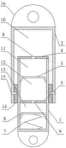
[0026] like figure 1 As shown, the multi-stage damping shock absorber includes an inner cylinder 1, an outer cylinder 2, a first floating piston 3, a first damping body 4, a second damping body 5, a second floating piston 6 and a spring 7; The upper end of the cylinder body 2 is closed, the lower end of the outer cylinder body 2 is open, the upper end of the inner cylinder body 1 is open, and the lower end of the inner cylinder body 1 is closed; A spring 7, a second floating piston 6, a second damping body 5 and a first floating piston 3 are arranged, one end of the spring 7 is connected to the second floating piston 6, and the other end of the spring 7 is connected to the bottom inner surface of the inner cylinder 1; The first damping body 4 is provided with a first damping hole 8, and the second damping body 5 is provided with a second damping hole 9; the inner cylinder 1 is slidably arranged in the outer cylinder 2, and the top end of the inner cylinder 1 is in contact with...

Embodiment 2

[0030] like figure 1 As shown, this embodiment is based on Embodiment 1, and a sealing support member 14 is provided between the bottom inner surface of the outer cylinder 2 and the outer surface of the inner cylinder 1 .

[0031] A sealing support member 8 is provided to prevent the oil in the outer cylinder 2 from leaking.

Embodiment 3

[0033] like figure 1 As shown, this embodiment is based on Embodiment 2, and the sealing support member 14 is connected to the outer cylindrical body 2 through a pin shaft 15 .


PUM


Abstract

The invention discloses a multistage damping shock-absorbing apparatus, which comprises an inner cylindrical shell, an outer cylindrical shell, a first floating piston, a first damping body, a second damping body, a second floating piston and a spring. The upper end of the outer cylindrical shell is closed; the lower end of the outer cylindrical shell is open; the upper end of the inner cylindrical shell is open; the lower end of the inner cylindrical shell is closed; the first damping body is arranged on the top of the inner cylindrical shell; the spring, the second floating piston, the second damping body and the first floating piston are arranged inside the inner cylindrical shell from top to bottom in order; one end of the spring is connected to the second floating piston and the other end of the spring is connected to the interior surface at the bottom of the inner cylindrical shell; a first damping aperture is drilled in the first damping body, and a second damping aperture is drilled in the second damping body; the inner cylindrical shell is arranged in the outer cylindrical shell in a sliding way; and an oil pressure space is formed between the top end of the inner cylindrical shell and the top end of the outer cylindrical shell. By adopting multistage pressure-relief, the shock-absorbing capability of a shock-absorbing apparatus is improved; at the same time, the requirement to the material intensity of the damping body is reduced; and the problem of over-hard performance of the shock-absorbing apparatus is solved.

Description

technical field [0001] The invention relates to the field of aircraft, in particular to a multi-stage damping shock absorber. Background technique [0002] Landing gear is a special device for aircraft to take off and land. During the landing process, the aircraft always hits the ground at a certain speed, and the landing gear bears and slows down this impact, thereby reducing the load on the aircraft. The key component of the landing gear to mitigate this impact load is the shock absorber. If the design of the shock absorber is unreasonable, the aircraft will bear a greater load, resulting in an increase in the design weight of the aircraft. If the shock absorber fails, it will lead to a hard landing of the aircraft, damage to the fuselage structure, and even a crash. [0003] The existing shock-absorbing equipment adopts an oil-air hybrid structure, and its disadvantage is that the air cavity is prone to leakage. Once the air cavity leaks, the cushioning effect of the ...

Claims


Application Information

Patent Timeline
IPC IPC(8): F16F9/18F16F9/32F16F9/34F16F9/36F16F13/00B64C25/58B64C25/60B64C25/62
Inventor 蒋磊
Owner 蒋磊
Why Eureka
Try Eureka