
Shockproof structure for battery modules

A battery module and anti-shock structure technology, which is applied in the direction of batteries, structural parts, battery pack parts, etc., to achieve the effect of convenient assembly

Inactive Publication Date: 2016-06-01
JIANGSU FGY ENERGY STORAGE RES INST
View PDF3 Cites 2 Cited by
  • Summary
  • Abstract
  • Description
  • Claims
  • Application Information

AI Technical Summary

Problems solved by technology

[0002] With the advancement of technology and the development of society, especially in industries that focus on environmental protection and high efficiency, battery packs have replaced some traditional energy sources. The battery pack is connected by multiple battery modules through copper bars. However, the traditional connection method It is to weld the sheet-shaped copper strips to the electrodes of the battery module. However, during the manufacture, transportation, and use of the battery pack, it is difficult to avoid machine vibrations. The vibrations cause deformation of the copper strips or battery poles, resulting in poor contact.

Method used


Image

  • Shockproof structure for battery modules

Examples


Embodiment Construction

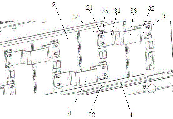
[0012] see figure 1 , the shockproof structure of the battery module, including a plurality of battery modules 2 arranged side by side, the battery module 2 is provided with a first electrode 21 and a second electrode 22, the first electrode 21 and the second electrode 22 are distributed along the vertical direction, the first electrode 21 Located above the second electrode 22, the polarity of the first electrode 21 and the second electrode 22 are opposite, if the first electrode 21 is positive, then the second electrode 22 is negative, if the first electrode 21 is negative, then the second electrode 22 is positive pole. The first electrodes 21 of two adjacent battery modules 2 are connected through the first conductive member 3, and the second electrodes 22 of two adjacent battery modules 2 are also connected through the second conductive member 4. The first conductive member 3 and the second conductive member The structures of the parts 4 are the same, and the first conduct...


PUM


Abstract

The invention provides a shockproof structure for battery modules. The shockproof structure comprises a plurality of battery modules which are arranged side by side, wherein each battery module is provided with a first electrode and a second electrode; two adjacent first electrodes are connected with each other through a first conductive part; two adjacent second electrodes are connected with each other through a second conductive part; the first conductive parts are the same as the second conductive parts in structure; the first conductive parts and the second conductive parts are distributed in a staggered manner up and down; each first conductive part comprises a first connection part, a second connection part and a convex buffer part; each first connection part and each second connection part are located at two ends; each convex buffer part is located in the middle part; two ends of each buffer part are connected with the corresponding first connection part and second connection part respectively; two connection holes distributed along the vertical direction are arranged on each first connection part and each second connection part; the connection holes are transverse waist-shaped holes; a conductive locating pin is arranged in each connection hole; each first conductive part is connected with the corresponding first electrode through the corresponding conductive locating pin; and each conductive locating pin can slide in the corresponding connection hole. The shockproof structure for the battery modules can play a shockproof role, and has the advantage of being convenient to assemble.

Description

technical field [0001] The invention relates to the field of power supply energy storage, in particular to a shockproof structure of a battery module. Background technique [0002] With the advancement of technology and the development of society, especially in industries that focus on environmental protection and high efficiency, battery packs have replaced some traditional energy sources. The battery pack is connected by multiple battery modules through copper bars. However, the traditional connection method It is to weld the sheet-shaped copper strips to the electrodes of the battery module. However, during the manufacture, transportation, and use of the battery pack, it is difficult to avoid machine vibrations. The vibrations cause deformation of the copper strips or battery poles, resulting in poor contact. [0003] Therefore, it is necessary to provide a novel shockproof structure of the battery module to solve the above problems. Contents of the invention [0004] ...

Claims


Application Information

Patent Timeline
Patent Type & Authority Applications(China)
IPC IPC(8): H01M2/20H01M2/34H01M2/10H01M50/204H01M50/502H01M50/55H01M50/572
CPCH01M2220/10H01M50/20H01M50/579H01M50/502Y02E60/10
Inventor 刘朔臻田维强司红磊李青海陈强
Owner JIANGSU FGY ENERGY STORAGE RES INST
Learn More