Camera component and terminal

A technology of camera assembly and camera module, which is applied in the directions of electrical components, image communication, color TV components, etc., can solve the problems of large tolerance accumulation, large volume, occupation of the overall structure of the camera assembly, etc., and achieves compact structure and improved structure. The effect of stability and structural stability

Active Publication Date: 2016-06-01
MEIZU TECH CO LTD
View PDF3 Cites 9 Cited by
  • Summary
  • Abstract
  • Description
  • Claims
  • Application Information

AI Technical Summary

Problems solved by technology

However, since the steel sheet itself has tolerances during stamping, and there are inevitably tolerances when spot welding the steel sheet to the camera module, the total tolerance accumulation is relatively large, resulting in the steel sheet after spot welding being connected obliquely to the camera module. On the module, the camera module will be connected to the terminal obliquely as a whole, and the surface of the camera module will not be flat
In mass production, the structural stability of the camera module is poor
In order to improve the structural stability of the camera module, the steel sheet will be bent so that part of the steel sheet is fixed on the end face of the camera module, and the other part is arranged on the side, thereby ensuring the structural stability of the steel sheet and the camera module. However, the steel sheet The chip will increase the overall thickness of the camera assembly, so that the overall structure of the camera assembly takes up a large volume and the stability is not good

Method used


Image

  • Camera component and terminal
  • Camera component and terminal
  • Camera component and terminal

Examples


no. 1 example

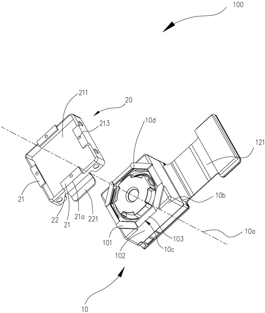
[0024] In the first embodiment, the camera module 10 is in the shape of a rectangular block. The end 10b is the top of the camera module 10, and the camera module also includes a bottom 12 opposite to the end 10b. The camera module 10 is provided with four sides 102 surrounding the end surface 101 . Four grooves 10 c are defined on the end surface 101 , and the four grooves 10 c are respectively arranged at four angles between the four side surfaces 102 and the end surface 101 . The end surface 101 is also provided with a lens hole 10d communicating with the groove 10c. The lens hole 10d is used to penetrate the scene light into the camera module 10, so that the camera module 10 can take pictures. The shooting main optical axis 10a coincides with the geometrical central axis of the lens hole 10c. The bottom end 12 may be connected with a flexible circuit board 121 , and the flexible circuit board 121 is used to electrically connect with the circuit board 30 . In other embod...


PUM


Abstract

The invention discloses a camera component and a terminal. The camera component comprises a camera module group and a fixing support. The camera module group is provided with a photographing primary optic axis and an end part which is arranged in the direction of the photographing primary optic axis. The end part comprises grooves which comprise a bottom surface perpendicular to the photographing primary optic axis. The fixing support comprises a top plate and at least two side plates. The top plate is accommodated in the grooves. The top plate comprises at least two edges which stretch out of the side surfaces. The at least two side plates are arranged at the circumferential side of the camera module group and are symmetrically arranged around the photographing primary optic axis. Each side plate is provided with a folding side which extends in a way of being parallel to the bottom surface. The folding sides are used for being carried on a circuit board. The top plate of the fixing support is fixed in the grooves of the end part so that the fixing support can be fixed on the camera module group, the fixing support is enabled to be structurally stable relative to the camera module group, and the overall thickness of the camera module group is not increased by the top plate.

Description

technical field [0001] The invention relates to the field of electronic equipment, in particular to a camera assembly and a terminal. Background technique [0002] At present, with the continuous maturity of modern technology, terminals are becoming lighter and lighter, especially thinner and thinner. However, because the rear camera module needs a certain fixed structure to connect with the terminal, after the terminal is thinned, the thickness of the camera module area cannot be reduced at the same time, so there is a problem that the camera module has a large part of the edge, which affects the appearance of the terminal. [0003] Therefore, in the prior art, there is a solution of spot-welding two steel sheets on the side of the camera module and overlapping them on the main board of the terminal. At this time, the connection between the camera module and the terminal is realized by spot-welding the steel sheets, and no setting is required. Fixed structures such as spec...

Claims


Application Information

Patent Timeline
Patent Type & Authority Applications(China)
IPC IPC(8): H04N5/225
CPCH04N23/57
Inventor 俞昌国
Owner MEIZU TECH CO LTD
Why Eureka
Try Eureka