
High pressure electric cooking pot

A high-voltage electric and hot pot technology, which is applied to pressure cookers, cooking utensil lids, cooking utensils, etc., can solve the problems of troublesome opening and closing of pot lids and cannot be used normally, and achieve the effect of convenient opening and closing of pot lids

Active Publication Date: 2016-06-08
中山市经贸纬进出口有限公司
View PDF4 Cites 58 Cited by
  • Summary
  • Abstract
  • Description
  • Claims
  • Application Information

AI Technical Summary

Problems solved by technology

However, in order to obtain a high-pressure cooking environment, the pressure cooker is equipped with a lid locking mechanism; and for the electric heating pot, which requires frequent opening and closing of the lid, if the existing structure of the pressure cooker is adopted, when the lid is opened and closed, Extremely troublesome, completely unusable

Method used


Image

  • High pressure electric cooking pot
  • High pressure electric cooking pot

Examples


Embodiment 1

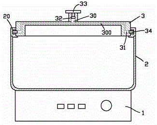
[0014] exist figure 1 In the shown embodiment one, the high-voltage electric heating pot includes a base 1, a pot body 2, and a pot cover 3; the upper port of the pot body 2 forms a horizontal ring groove 20, and the notch of the horizontal ring groove 20 faces the pot Inside; the center of the pot cover 3 vertically upwards to form a central slideway 30, and the central slideway 30 is connected to the horizontal slideway 31 symmetrically arranged on both sides of the pot cover through the hole 300; the inside of the central slideway 30 A vertically movable central slide 32 is provided, and the central slide 32 is vertically connected to the lid handle 33; the horizontal slide 31 is provided with a horizontally movable horizontal slide 34, and the horizontal slide The block 34 is matched with the horizontal ring groove 20; the channel between the central slide 32 and the transverse slide 34 is filled with liquid, and when the central slide 32 drops to the lower limit position,...

Embodiment 2

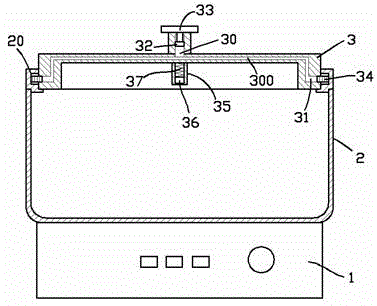
[0018] for figure 2 The second embodiment shown is different from the first embodiment in that: the center of the pot cover 3 extends vertically downwards with a lower slideway 35, and a permanent magnetic slideway 35 is provided in the lower slideway 35. block 36, and between the permanent magnet slider 36 and the bottom end of the lower slideway 35, a vacuum is provided, and a support spring 37 is provided; when the permanent magnet slider 36 is in the lower limit position, the support spring The elastic force of 37 is balanced with the standard atmospheric pressure; when the permanent magnet slider 36 is subjected to an upward pressure greater than 1 standard atmospheric pressure, it moves upward and further compresses the support spring 37 until the permanent magnet slider 36 is stressed balanced; the central slide 32 is also composed of permanent magnets, and is opposite to the same pole of the permanent magnet slider 36; the permanent magnet slider 36 has slid to the up...


PUM


Abstract

The invention provides a high pressure electric cooking pot which comprises a base, a pot body and a pot cover. A horizontal annular groove is formed in the upper port of the pot body, and the opening of the horizontal annular groove faces the interior of the pot. A central sliding way is vertically formed in the center of the pot cover upwards. The central sliding way is communicated to transverse sliding ways symmetrically arranged on the two sides of the pot cover through hole channels. A central sliding piston capable of moving vertically is arranged in the central sliding way. The central sliding piston is vertically connected to a pot cover handle upwards. Transverse sliding blocks capable of transversely moving are arranged in the transverse sliding ways and matched with the horizontal annular groove. The channel between the central sliding piston and each transverse sliding block is filled with fluid. When the central sliding piston descends to the lowest position, the transverse sliding blocks transversely stretch into the horizontal annular groove; when the central sliding piston ascends to the uppermost position, the transverse sliding blocks transversely stretch out of the horizontal annular groove. High-pressure cooking environment can be formed in the high pressure electric cooking pot, and opening and closing of the pot cover are quite convenient.

Description

technical field [0001] The invention relates to the field of kitchen electrical equipment, in particular to an electric heating pan. Background technique [0002] Electric hot pots are popular because of their convenience. People usually cook and eat the ingredients in the electric hot pot. During this process, it is usually necessary to lift the lid from time to time to check the degree of cooking of the food. On the other hand, as we all know, for a pressure cooker, the food inside can get a higher cooking temperature, so that it is easier to cook the food and it is more conducive to sterilization. However, in order to obtain a high-pressure cooking environment, the pressure cooker is equipped with a lid locking mechanism; and for the electric heating pot, which requires frequent opening and closing of the lid, if the existing structure of the pressure cooker is adopted, when the lid is opened and closed Extremely troublesome and completely unusable. Contents of the...

Claims


Application Information

Patent Timeline
IPC IPC(8): A47J36/06A47J36/10
CPCA47J27/08A47J27/0815A47J27/092A47J36/06A47J36/10
Inventor 钱月珍
Owner 中山市经贸纬进出口有限公司
Features
  • Generate Ideas
  • Intellectual Property
  • Life Sciences
  • Materials
  • Tech Scout
  • Unparalleled Data Quality
  • Higher Quality Content
  • 60% Fewer Hallucinations
Learn More