
Push bending equipment for pipe or profile

A profile and pipe technology, which is applied in the field of push bending equipment, can solve the problems of inability to process bent pipe products that meet the size requirements, large thrust, and large amount of material rebound, so as to achieve automatic operation, low manufacturing cost, and guaranteed bending quality Effect

Active Publication Date: 2018-08-21
ZHANGJIAGANG MINGHUA MACHINERY MFG
View PDF5 Cites 0 Cited by
  • Summary
  • Abstract
  • Description
  • Claims
  • Application Information

AI Technical Summary

Problems solved by technology

[0002] Existing push bending equipment is difficult to bend some large-scale pipes or profiles, because this kind of bending process not only requires a large thrust, but also needs to achieve continuous bending. In addition, the rebound of the material after bending is large. There are equipments that cannot process finished pipe bends that meet the size requirements

Method used


Image

  • Push bending equipment for pipe or profile
  • Push bending equipment for pipe or profile
  • Push bending equipment for pipe or profile

Examples


Embodiment Construction

[0033] The specific implementation of the present invention will be described in detail below with reference to the accompanying drawings, taking push-bending pipes as an example.

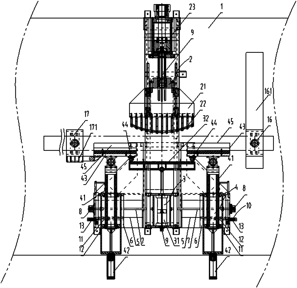
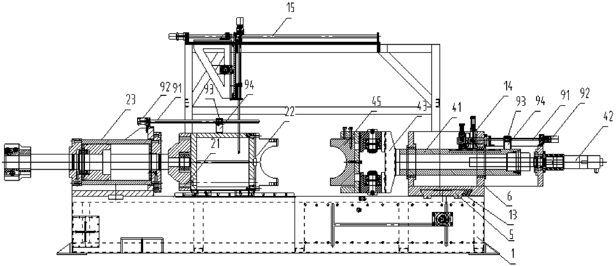
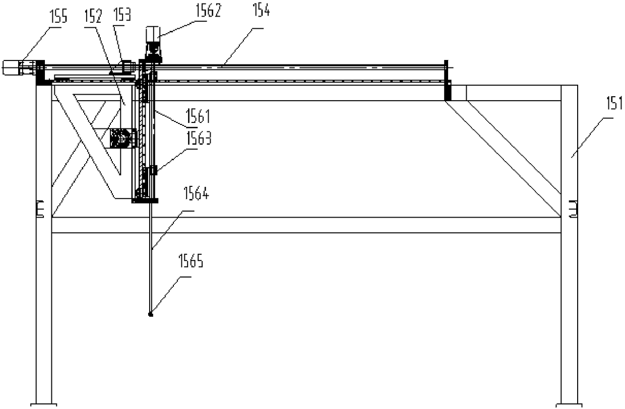
[0034] Such as Figure 1-2As shown, a push bending equipment for pipes includes a machine platform 1, a push bending mechanism is provided on the machine platform 1, a push bending radius measuring mechanism 15 is provided on the machine platform 1 above the push bending mechanism, and a push bending radius measuring mechanism 15 is arranged on the machine platform 1. The feed side of the bending mechanism is provided with a feed clamping mechanism 17, and the machine table 1 is provided with a discharge clamping mechanism 16 on the discharge side of the push bending mechanism.

[0035] The push-bending mechanism includes a main push-bending die device 2 arranged on the machine platform 1. A reverse thrust support device 3 is provided on the machine platform 1 at a position facing the push-bend mai...


PUM

PropertyMeasurementUnit
thicknessaaaaaaaaaa
diameteraaaaaaaaaa

Abstract

The invention discloses push bending equipment of pipes or sections. The push bending equipment comprises an equipment stand, a push bending mechanism is arranged on the equipment stand, a push bending radius measuring mechanism is arranged at a position, above the push bending mechanism, of the equipment stand, a feeding clamping mechanism and a discharging clamping mechanism are arranged on the equipment stand, the push bending mechanism comprises a push bending main mold device and a reverse push supporting device, sliding plate mold devices are arranged at positions, on two sides of the reverse push supporting device, of the equipment stand, the push bending main mold device comprises a main mold seat slidably arranged on the equipment stand, a push bending main mold is detachably arranged on the main mold seat, an arc-shaped forming groove is formed in a forming end of the push bending main mold, and a main oil cylinder driving the main mold seat to move is arranged on the equipment stand; the reverse push supporting device comprises a supporting oil cylinder and a supporting seat, each sliding plate mold device comprises a moving seat slidably arranged on the equipment stand and an auxiliary oil cylinder driving the moving seat, a sliding mold seat is hinged on each moving seat, a sliding plate mold is detachably arranged on each sliding mold seat, and a push bending straight groove is formed in each sliding plate mold. The push bending equipment can bend the pipes or the sections which are large in bending radius and accurate in forming.

Description

technical field [0001] The invention relates to a push-bending device for pipes or profiles. Background technique [0002] Existing push bending equipment is difficult to bend some large-scale pipes or profiles, because this kind of bending process not only requires a large thrust, but also needs to achieve continuous bending. In addition, the rebound of the material after bending is large. Some equipment cannot process finished bent pipes that meet the size requirements. For example, when processing bridge pipes with a bending radius of more than 4 times the diameter of the pipe, a wall thickness of more than 25mm, and a diameter of more than 400mm, the current general processing method is to use a rounding machine to roll them piece by piece and weld them together to form. Contents of the invention [0003] The technical problem to be solved by the present invention is to provide a push-bending device capable of bending large-bending radius and accurately formed pipes o...

Claims


Application Information

Patent Timeline
Patent Type & Authority Patents(China)
IPC IPC(8): B21D7/025B21D7/14
CPCB21D7/025B21D7/14
Inventor 贾卫锋
Owner ZHANGJIAGANG MINGHUA MACHINERY MFG
Learn More